Infiniti I35 (A33). Manual — part 558
2.
Apply water again to all radiator core surfaces once per
minute.
3.
Stop washing if any stains no longer flow out from the radia-
tor.
4.
Blow air into the back side of radiator core vertically downward.
I
Use compressed air lower than 490 kPa (5 kg/cm
2
, 71 psi) and
keep distance more than 30 cm (11.8 in).
5.
Blow air again into all the radiator core surfaces once per
minute until no water sprays out.
SLC755A
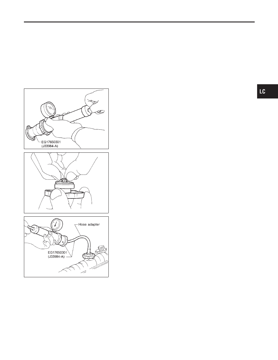
CHECKING RADIATOR CAP
NHLC0016S03
To check radiator cap, apply pressure to cap with a tester.
Radiator cap relief pressure:
Standard
78 - 98 kPa
(0.8 - 1.0 kg/cm
2
, 11 - 14 psi)
Limit
59 kPa
(0.6 kg/cm
2
, 9 psi)
SMA967B
Pull the negative pressure valve to open it.
Check that it closes completely when released.
SLC756A
CHECKING COOLING SYSTEM FOR LEAKS
NHLC0016S04
To check for leakage, apply pressure to the cooling system with a
tester.
Testing pressure:
157 kPa (1.6 kg/cm
2
, 23 psi)
CAUTION:
Higher than the specified pressure may cause radiator dam-
age.
NOTE:
In the case that engine coolant decreases, replenish radiator
with engine coolant.
GI
MA
EM
EC
FE
AT
AX
SU
BR
ST
RS
BT
HA
SC
EL
IDX
ENGINE COOLING SYSTEM
System Check (Cont’d)
LC-13
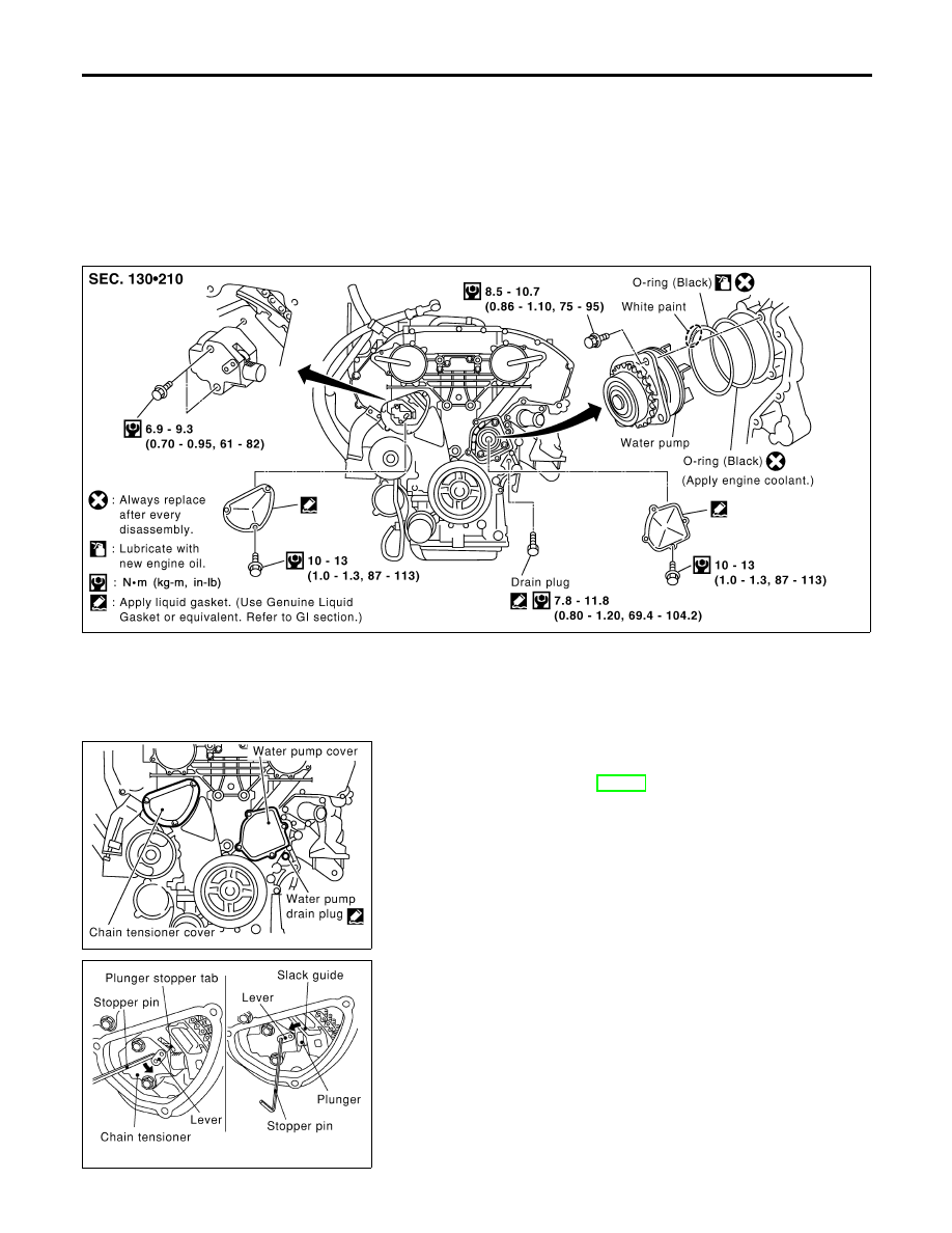
Water Pump
REMOVAL AND INSTALLATION
=NHLC0017
CAUTION:
I
When removing water pump assembly, be careful not to
get coolant on drive belt.
I
Water pump cannot be disassembled and should be
replaced as a unit.
I
After installing water pump, connect hose and clamp
securely, then check for leaks using radiator cap tester.
SLC523B
SLC443B
REMOVAL
NHLC0018
1.
Drain coolant from drain plugs on radiator and right side of
cylinder block. Refer to MA-14, “Changing Engine Coolant”.
2.
Remove right side engine mounting, mounting bracket and
nuts.
3.
Remove drive belts and idler pulley bracket.
4.
Remove water pump drain plug.
5.
Remove chain tensioner cover and water pump cover.
SLC444B
6.
Pull lever down, and release plunger stopper tab.
I
Plunger stopper tab can be pushed up to release (coaxial
structure with lever).
7.
Insert stopper pin into tensioner body hole to fix lever, and
keep the tab released.
8.
Insert plunger into tensioner body by pressing slack guide.
9.
Keep slack guide pressed, and fix it by pushing stopper pin
through lever hole and body hole.
ENGINE COOLING SYSTEM
Water Pump
LC-14
SLC445B
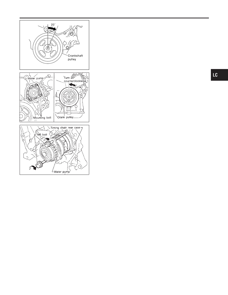
10. Turn crankshaft pulley approx. 20° clockwise so that the tim-
ing chain on the chain tensioner side is loose.
11. Remove chain tensioner.
CAUTION:
Be careful not to drop mounting bolts inside chain case.
SLC941A
12. Loosen the 3 water pump fixing bolts. Secure a gap between
water pump gear and timing chain, by turning crankshaft pul-
ley 20° backwards.
SLC942A
13. Put M8 bolts [pitch: 1.25 mm (0.0492 in) length: approx. 50 mm
(1.97 in)] to two M8-threaded holes out of 3 water pump fixing
bolt holes.
GI
MA
EM
EC
FE
AT
AX
SU
BR
ST
RS
BT
HA
SC
EL
IDX
ENGINE COOLING SYSTEM
Water Pump (Cont’d)
LC-15
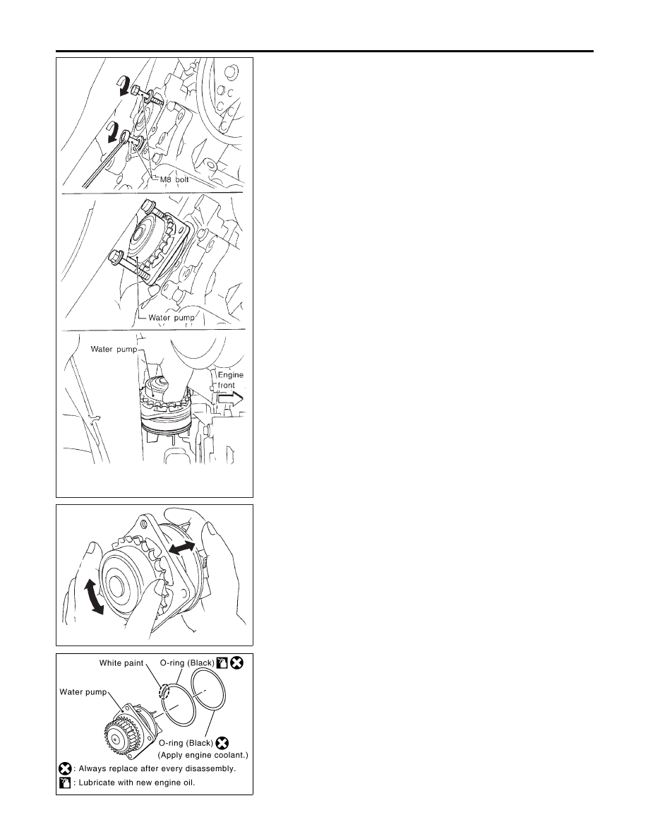
SLC116B
14. Tighten M8 bolts by turning half turn alternately until they reach
timing chain rear case.
I
In order to prevent damages to water pump or timing chain rear
case, do not tighten one bolt continuously. Always turn each
bolt half turn each time.
15. Lift up water pump and remove it.
I
When lifting up water pump, do not allow water pump gear to
hit timing chain.
SLC943A
INSPECTION
NHLC0019
1.
Check for badly rusted or corroded body assembly.
2.
Check for rough operation due to excessive end play.
SLC524B
INSTALLATION
NHLC0020
1.
Apply engine oil and coolant to O-rings as shown in the figure.
I
Install O-ring with a white paint mark to the front side.
ENGINE COOLING SYSTEM
Water Pump (Cont’d)
LC-16
Нет комментариевНе стесняйтесь поделиться с нами вашим ценным мнением.
Текст