Infiniti I35 (A33). Manual — part 556
SLC492B
GI
MA
EM
EC
FE
AT
AX
SU
BR
ST
RS
BT
HA
SC
EL
IDX
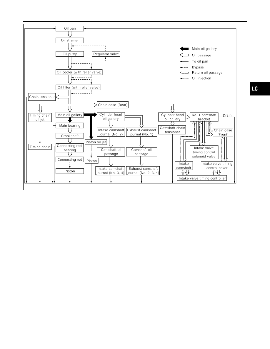
ENGINE LUBRICATION SYSTEM
Lubrication Circuit (Cont’d)
LC-5
SLC240B
SLC926
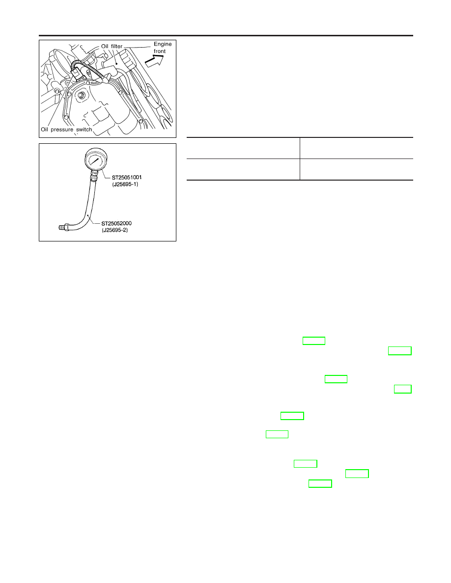
Oil Pressure Check
=NHLC0004
WARNING:
I
Be careful not to burn yourself, as the engine and oil may
be hot.
I
Oil pressure check should be done in “Parking position”.
1.
Check oil level.
2.
Remove oil pressure switch.
3.
Install pressure gauge.
4.
Start engine and warm it up to normal operating temperature.
5.
Check oil pressure with engine running under no-load.
Engine speed
rpm
Approximate discharge pressure
kPa (kg/cm
2
, psi)
Idle speed
2,000
More than 98 (1.0, 14)
294 (3.0, 43)
If difference is extreme, check oil passage and oil pump
for oil leaks.
6.
Install oil pressure switch with sealant.
Oil Pump
REMOVAL AND INSTALLATION
NHLC0005
CAUTION:
When removing the oil pans, oil pump assembly and timing
chain from engine, first remove the crankshaft position sensor
(POS) from the assembly.
Be careful not to damage sensor edge.
1.
Drain engine oil.
To avoid the danger of being scalded, never drain the
engine oil when the engine is hot.
2.
Remove drive belts. Refer to MA-13, “Checking Drive Belts”.
3.
Remove crankshaft position sensor (POS). Refer to EM-14,
“Components”.
4.
Remove engine under covers.
5.
Remove crankshaft pulley. Refer to EM-29, “Components”.
6.
Remove front exhaust tube and its support. Refer to FE-9,
“Removal and Installation”.
7.
Support engine at right and left side engine slingers with a
suitable hoist. Refer to EM-70, “Removal”.
8.
Remove engine right side mounting insulator and bracket bolts
and nuts. Refer to EM-69, “Removal and Installation”.
9.
Remove center member assembly.
10. Remove air conditioner compressor assembly and bracket.
11. Remove oil pans. Refer to EM-14, “Removal”.
12. Remove front timing chain case. Refer to EM-21, “Removal”.
13. Remove timing chain. Refer to EM-32, “Removal”.
14. Remove oil pump assembly.
15. Reinstall any parts removed in reverse order of removal.
ENGINE LUBRICATION SYSTEM
Oil Pressure Check
LC-6
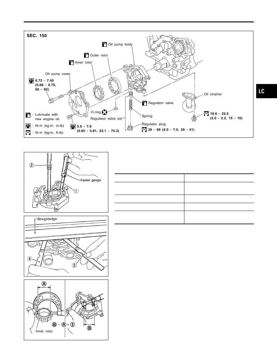
DISASSEMBLY AND ASSEMBLY
NHLC0006
SLC464B
I
When installing oil pump, apply engine oil to rotors.
SLC932A
SLC933A
OIL PUMP INSPECTION
NHLC0007
Using a feeler gauge, straightedge and micrometers, check the
following clearances:
Unit: mm (in)
Body to outer rotor radial clearance 1
0.114 - 0.260 (0.0045 - 0.0102)
Inner rotor to outer rotor tip clearance
2
Below 0.18 (0.0071)
Body to inner rotor axial clearance 3
0.030 - 0.070 (0.0012 - 0.0028)
Body to outer rotor axial clearance 4
0.050 - 0.110 (0.0020 - 0.0043)
Inner rotor to brazed portion of hous-
ing clearance 5
0.045 - 0.091 (0.0018 - 0.0036)
I
If the tip clearance (2) exceeds the limit, replace rotor set.
I
If body to rotor clearances (1, 3, 4, 5) exceed the limit,
replace oil pump body assembly.
SLC934AB
GI
MA
EM
EC
FE
AT
AX
SU
BR
ST
RS
BT
HA
SC
EL
IDX
ENGINE LUBRICATION SYSTEM
Oil Pump (Cont’d)
LC-7
SLC251B
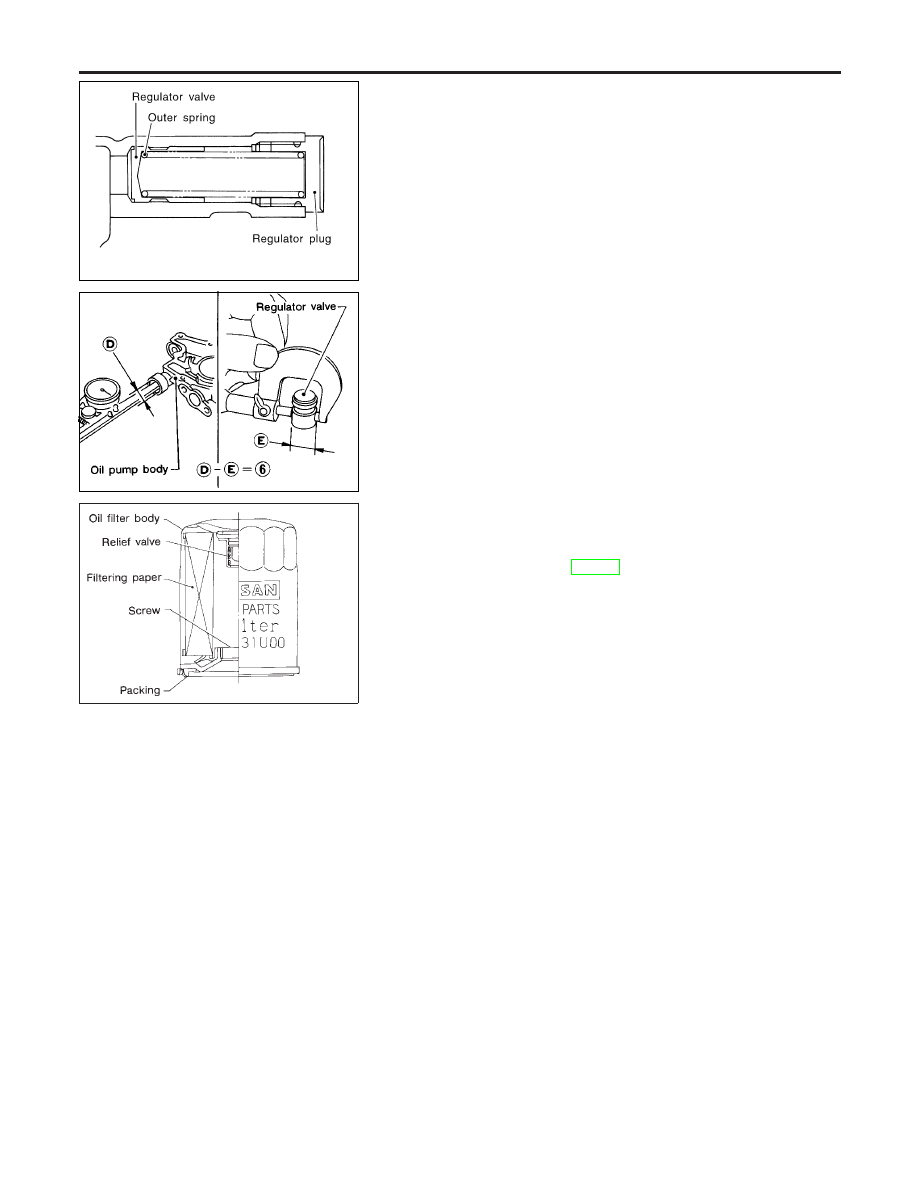
REGULATOR VALVE INSPECTION
NHLC0008
1.
Visually inspect components for wear and damage.
2.
Check oil pressure regulator valve sliding surface and valve
spring.
3.
Coat regulator valve with engine oil. Check that it falls
smoothly into the valve hole by its own weight.
If damaged, replace regulator valve set or oil pump body.
SLC935AA
4.
Check regulator valve to oil pump body clearance.
Clearance:
6 : 0.040 - 0.097 mm (0.0016 - 0.0038 in)
If it exceeds the limit, replace oil pump body.
SLC035B
Oil Filter
NHLC0009
The oil filter is a small, full-flow cartridge type and is provided with
a relief valve.
I
Use Tool specified in MA-17 for changing oil filter.
ENGINE LUBRICATION SYSTEM
Oil Pump (Cont’d)
LC-8
Нет комментариевНе стесняйтесь поделиться с нами вашим ценным мнением.
Текст