Infiniti I35 (A33). Manual — part 559
SLC031B
2.
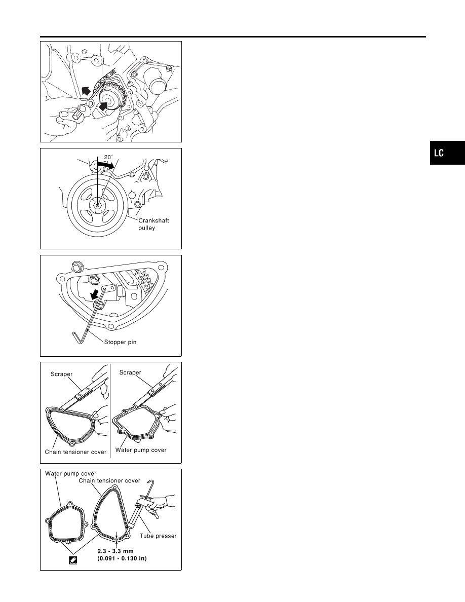
Install water pump.
I
Do not allow cylinder block to nip O-rings when installing
water pump.
SLC445B
3.
Return the crankshaft pulley to its original position by turning
it 20° forward.
SLC448B
4.
Install timing chain tensioner, then remove the stopper pin.
I
When installing the timing chain tensioner, engine oil
should be applied to the oil hole and tensioner.
SLC446B
5.
Install chain tensioner cover and water pump cover.
a.
Before installing, remove all traces of liquid gasket from mat-
ing surface of water pump cover and chain tensioner cover
using a scraper.
Also remove traces of liquid gasket from mating surface of
front cover.
SLC447B
b.
Apply a continuous bead of liquid gasket to mating surface of
chain tensioner cover and water pump cover.
6.
Install drain plug on cylinder block.
7.
Reinstall any parts removed in reverse order of removal.
I
After starting engine, let idle for three minutes, then rev
engine up to 3,000 rpm under no load to purge air from the
high-pressure chamber of the chain tensioners. The
engine may produce a rattling noise. This indicates that
air still remains in the chamber and is not a matter of
concern.
GI
MA
EM
EC
FE
AT
AX
SU
BR
ST
RS
BT
HA
SC
EL
IDX
ENGINE COOLING SYSTEM
Water Pump (Cont’d)
LC-17
Thermostat
REMOVAL AND INSTALLATION
NHLC0021
SLC449BA
SLC962AB
1.
Drain coolant from drain plugs on radiator and both sides of
cylinder block.
2.
Remove drive belts and idler pulley bracket.
3.
Remove water pump drain plug on pump side of cylinder block.
4.
Remove lower radiator hose.
5.
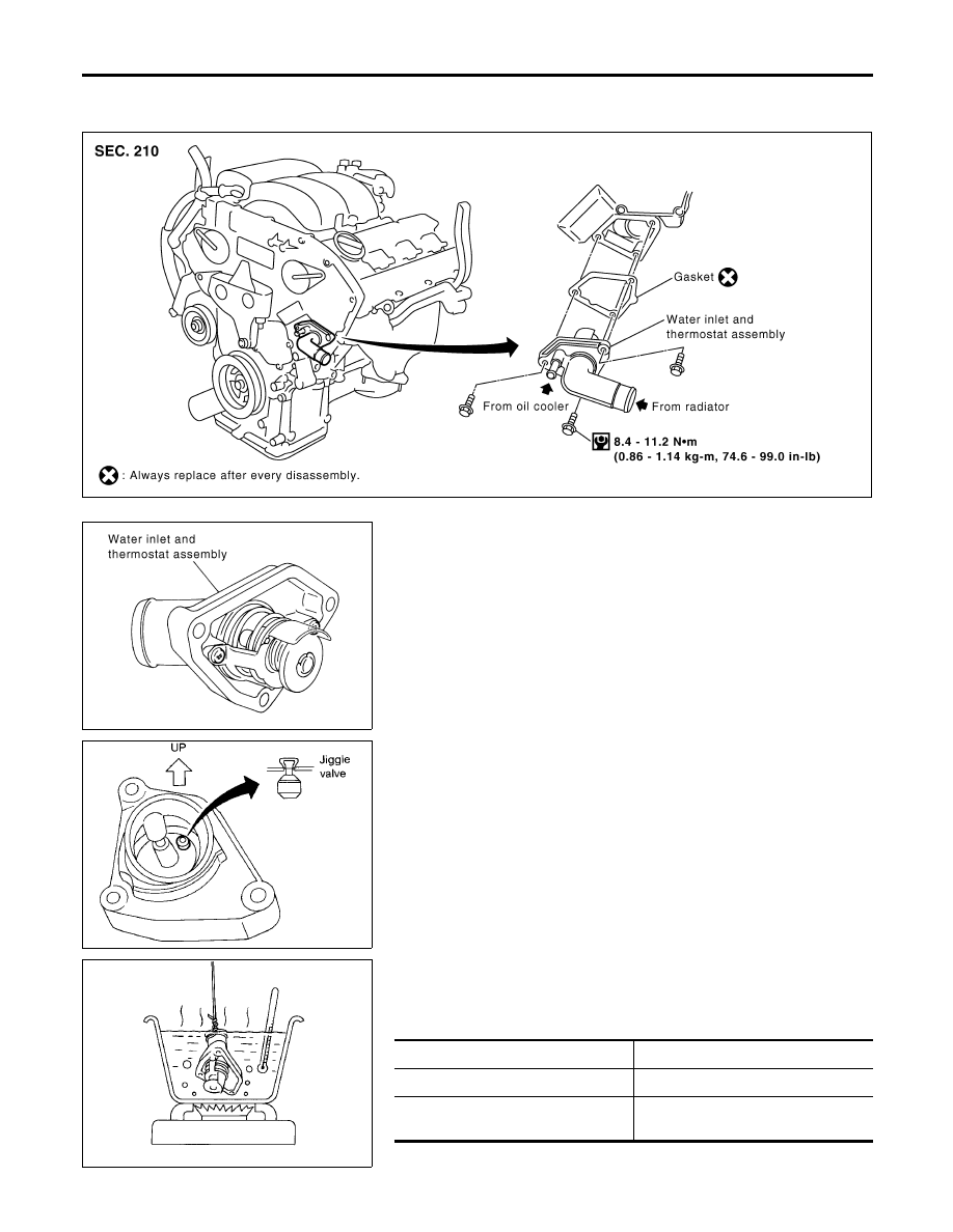
Remove water inlet and thermostat assembly.
I
Do not disassemble water inlet and thermostat. Replace
them as a unit, if necessary.
SLC948A
6.
Install thermostat with jiggle valve facing upward.
I
After installation, run engine for a few minutes, and check
for leaks.
I
Be careful not to spill coolant over engine compartment.
Use a rag to absorb coolant.
SLC949A
INSPECTION
NHLC0022
1.
Check valve seating condition at ordinary room temperatures.
It should seat tightly.
2.
Check valve opening temperature and maximum valve lift.
Standard
Valve opening temperature
82°C (180°F)
Valve lift
More than 8.6 mm/95°C
(0.339 in/203°F)
ENGINE COOLING SYSTEM
Thermostat
LC-18
3.
Then check if valve closes at 5°C (9°F) below valve opening
temperature.
Water Outlet and Water Piping
REMOVAL AND INSTALLATION
NHLC0032
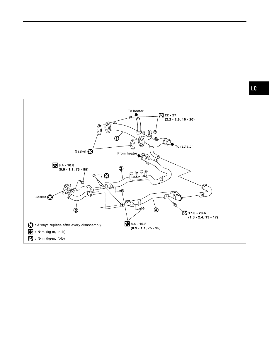
SLC450BA
1.
Water outlet
2.
Heater pipe
3.
Water connector
4.
Water bypass pipe
1.
Drain coolant from drain plugs on radiator and both sides of
cylinder block.
2.
Remove water connector, heater pipe and water bypass pipe.
3.
Install in the reverse order of removal.
I
After installation, run engine for a few minutes, and check
for leaks.
I
Be careful not to spill coolant over engine compartment.
Use a rag to absorb coolant.
GI
MA
EM
EC
FE
AT
AX
SU
BR
ST
RS
BT
HA
SC
EL
IDX
ENGINE COOLING SYSTEM
Thermostat (Cont’d)
LC-19
Radiator
REMOVAL AND INSTALLATION
=NHLC0023
1. Remove under cover.
2. Drain coolant from radiator.
3. Disconnect radiator upper and lower hoses.
4. Remove radiator shroud.
5. Remove A/T oil cooler hoses.
6. Disconnect reservoir tank hose.
7. Remove radiator mounting bracket.
8. Remove radiator.
9. After repairing or replacing radiator, install any part removed in reverse order of removal.
When filling radiator with coolant, refer to MA-14, “Changing Engine Coolant”.
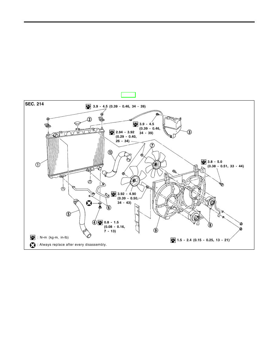
SLC491B
1.
Radiator
2.
Radiator cap
3.
Reservoir tank
4.
Radiator drain plug
5.
Upper radiator hose
6.
Oil cooler hoses
7.
Cooling fans
8.
Cooling fan motors
9.
Radiator shroud
10. Lower radiator hose
ENGINE COOLING SYSTEM
Radiator
LC-20
Нет комментариевНе стесняйтесь поделиться с нами вашим ценным мнением.
Текст