Infiniti I35 (A33). Manual — part 557
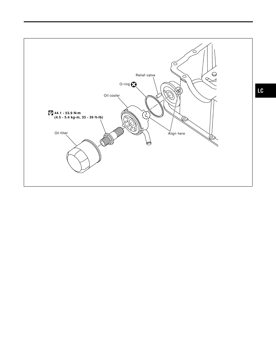
Oil Cooler
NHLC0037
REMOVAL AND INSTALLATION
NHLC0037S01
SLC440B
1.
Drain engine oil and coolant.
2.
Remove oil cooler.
3.
Installation is in reverse order of removal.
I
Do not spill coolant on the drive belt.
I
Install oil cooler to oil pan aligning the protrusion of flange
as shown.
INSPECTION
NHLC0037S02
Oil Cooler
NHLC0037S0201
1.
Check oil cooler for cracks.
2.
Check oil cooler for clogging by blowing through coolant inlet.
If necessary, replace oil cooler assembly.
Relief Valve
NHLC0037S0202
Inspect relief valve for movement, cracks and breaks by pushing
the ball. If replacement is necessary, remove valve by prying it out
with a suitable tool. Install a new valve in place by tapping it.
GI
MA
EM
EC
FE
AT
AX
SU
BR
ST
RS
BT
HA
SC
EL
IDX
ENGINE LUBRICATION SYSTEM
Oil Cooler
LC-9
Service Data and Specifications (SDS)
OIL PRESSURE
=NHLC0010
Engine speed
rpm
Approximate discharge pressure
kPa (kg/cm
2
, psi)
Idle speed
2,000
More than 98 (1.0, 14)
294 (3.0, 43)
REGULATOR VALVE
NHLC0011
Unit: mm (in)
Regulator valve to oil pump cover clearance
0.040 - 0.097 (0.0016 - 0.0038)
OIL PUMP
NHLC0012
Unit: mm (in)
Body to outer rotor radial clearance
0.114 - 0.260 (0.0045 - 0.0102)
Inner rotor to outer rotor tip clearance
Below 0.18 (0.0071)
Body to inner rotor axial clearance
0.030 - 0.070 (0.0012 - 0.0028)
Body to outer rotor axial clearance
0.050 - 0.110 (0.0020 - 0.0043)
Inner rotor to brazed portion of housing clearance
0.045 - 0.091 (0.0018 - 0.0036)
ENGINE LUBRICATION SYSTEM
Service Data and Specifications (SDS)
LC-10
SEM164F
AEM080
Precautions
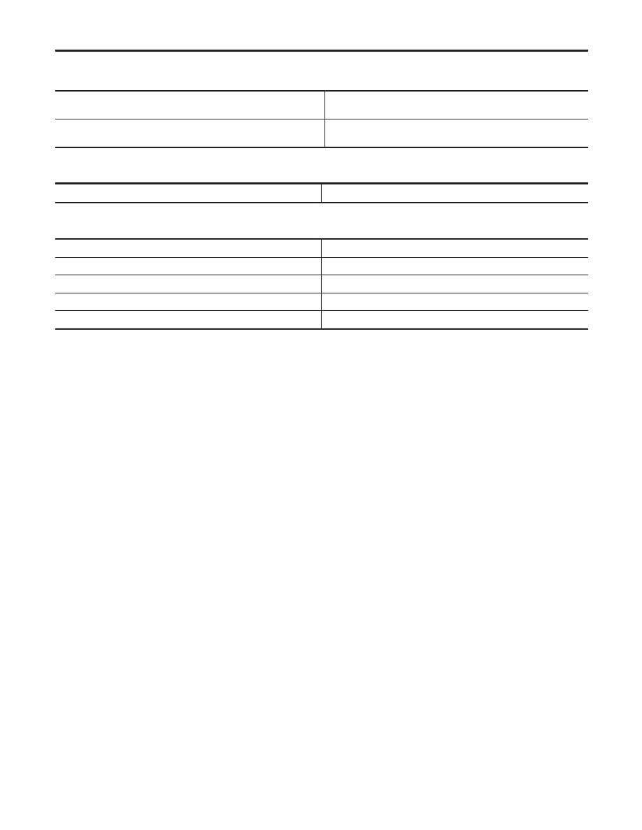
LIQUID GASKET APPLICATION PROCEDURE
NHLC0013
1.
Use a scraper to remove all traces of old liquid gasket from
mating surfaces and grooves. Also, completely clean any oil
from these areas.
2.
Apply a continuous bead of liquid gasket to mating surfaces.
(Use Genuine RTV silicone sealant or equivalent. Refer to
GI-53.)
I
Be sure liquid gasket diameter is 2.3 to 3.3 mm (0.091 to 0.130
in).
3.
Apply liquid gasket around the inner side of bolt holes (unless
otherwise specified).
4.
Assembly should be done within 5 minutes after coating.
5.
Wait at least 30 minutes before refilling engine oil and engine
coolant.
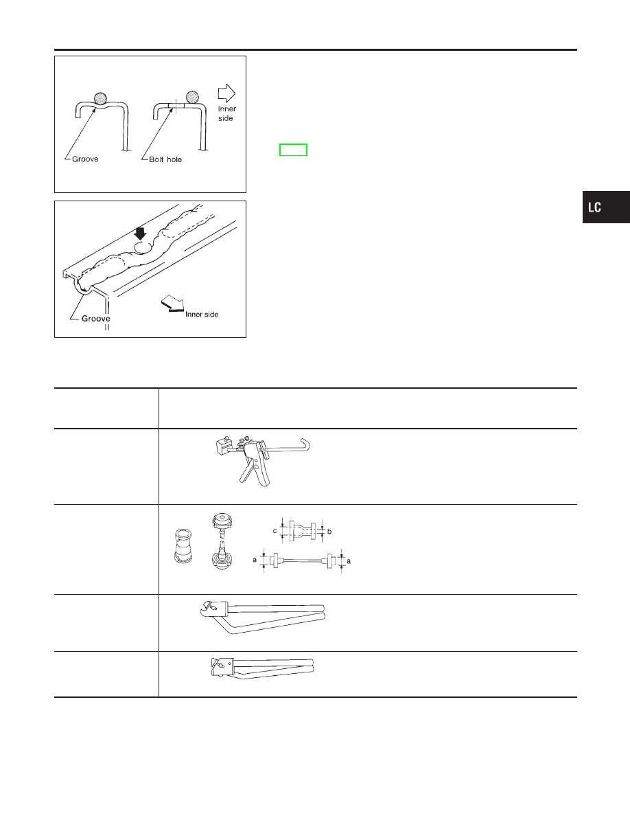
Preparation
SPECIAL SERVICE TOOLS
NHLC0014
The actual shapes of Kent-Moore tools may differ from those of special service tools illustrated here.
Tool number
(Kent-Moore No.)
Tool name
Description
WS39930000
(
—
)
Tube pressure
NT052
Pressing the tube of liquid gasket
EG17650301
(J33984-A)
Radiator cap tester
adapter
NT564
Adapting radiator cap tester to radiator filler neck
a: 28 (1.10) dia.
b: 31.4 (1.236) dia.
c: 41.3 (1.626) dia.
Unit: mm (in)
KV99103510
(
—
)
Radiator plate pliers A
NT224
Installing radiator upper and lower tanks
KV99103520
(
—
)
Radiator plate pliers B
NT225
Removing radiator upper and lower tanks
GI
MA
EM
EC
FE
AT
AX
SU
BR
ST
RS
BT
HA
SC
EL
IDX
ENGINE COOLING SYSTEM
Precautions
LC-11
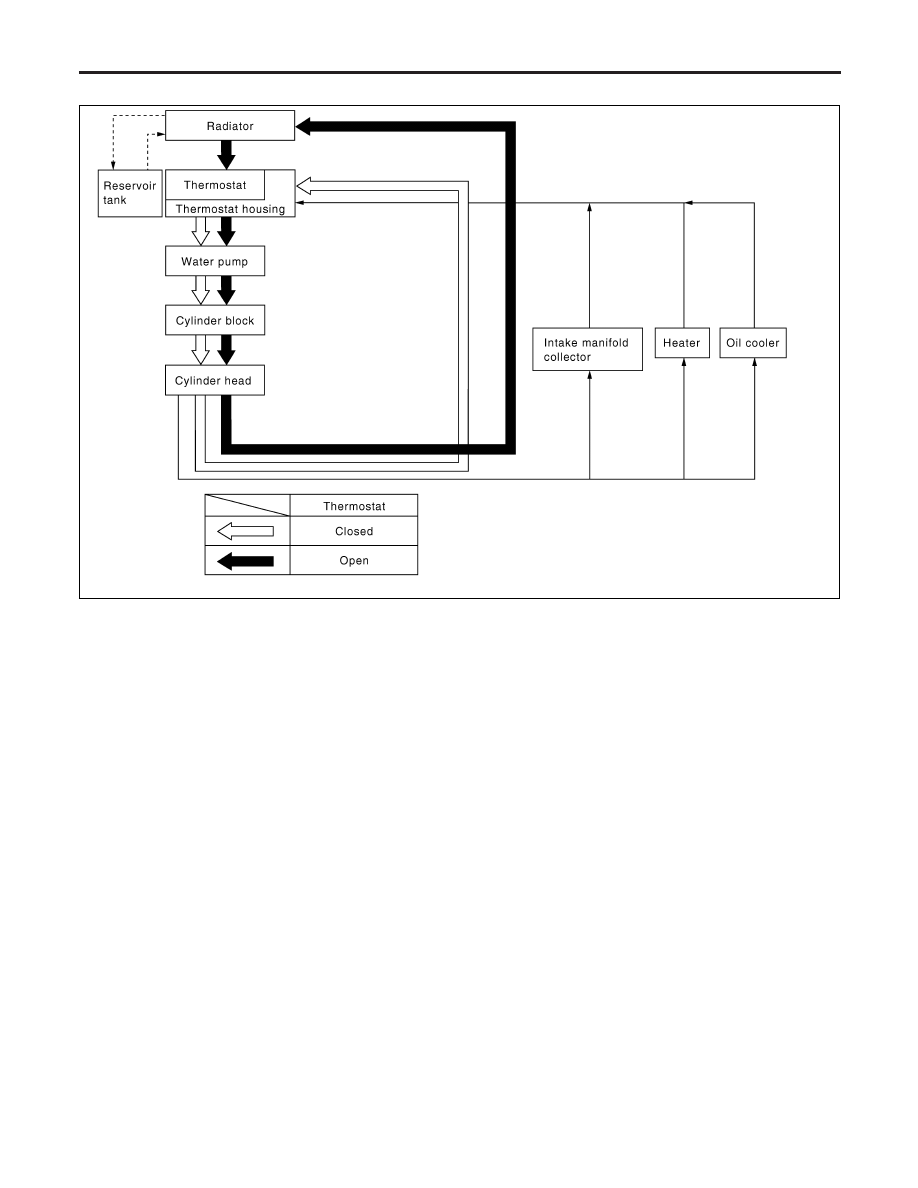
Cooling Circuit
NHLC0038
SLC520B
System Check
NHLC0016
WARNING:
Never remove the radiator cap when the engine is hot; serious
burns could be caused by high pressure fluid escaping from
the radiator.
Wrap a thick cloth around the cap and carefully remove it by
turning it a quarter turn to allow built-up pressure to escape
and then turn the cap all the way off.
CHECKING COOLING SYSTEM HOSES
NHLC0016S01
Check hoses for improper attachment, leaks, cracks, damage,
loose connections, chafing and deterioration.
CHECKING RADIATOR
NHLC0016S02
Check radiator for mud or clogging. If necessary, clean radiator as
follows.
I
Be careful not to bend or damage the radiator fins.
I
When radiator is cleaned without removal, remove all sur-
rounding parts such as cooling fan, radiator shroud and horns.
Then tape the harness and connectors to prevent water from
entering.
1.
Apply water by hose to the back side of the radiator core ver-
tically downward.
ENGINE COOLING SYSTEM
Cooling Circuit
LC-12
Нет комментариевНе стесняйтесь поделиться с нами вашим ценным мнением.
Текст