Infiniti M35/M45 Y50. Manual — part 710
DTC P1805 BRAKE SWITCH
EC-1313
[VK45DE]
C
D
E
F
G
H
I
J
K
L
M
A
EC
ASCD MODELS
1.
CHECK STOP LAMP SWITCH CIRCUIT
1.
Turn ignition switch OFF.
2.
Check the stop lamp when depressing and releasing the brake pedal.
OK or NG
OK
>> GO TO 4.
NG
>> GO TO 2.
2.
CHECK STOP LAMP SWITCH POWER SUPPLY CIRCUIT
1.
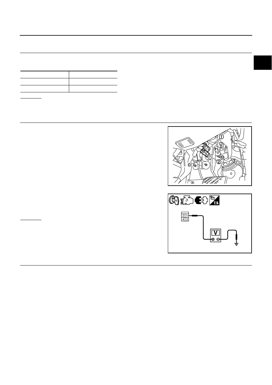
Disconnect stop lamp switch (1) harness connector.
–
ASCD brake switch (2)
2.
Check voltage between stop lamp switch terminal 1 and ground
with CONSULT -II or tester.
OK or NG
OK
>> GO TO 4.
NG
>> GO TO 3.
3.
DETECT MALFUNCTIONING PART
Check the following.
●
Fuse block (J/B) connector E101
●
10A fuse
●
Harness for open or short between stop lamp switch and battery
>> Repair open circuit or short to ground or short to power in harness or connectors.
Brake pedal
Stop lamp
Fully released
Not illuminated
Slightly depressed
Illuminated
PBIB2705E
Voltage: Battery voltage
PBIA9488J

EC-1314
[VK45DE]
DTC P1805 BRAKE SWITCH
4.
CHECK STOP LAMP SWITCH INPUT SIGNAL CIRCUIT FOR OPEN AND SHORT
1.
Disconnect ECM harness connector.
2.
Check harness continuity between ECM terminal 101 and stop lamp switch terminal 2.
Refer to Wiring Diagram.
3.
Also check harness for short to ground and short to power.
OK or NG
OK
>> GO TO 6.
NG
>> GO TO 5.
5.
DETECT MALFUNCTIONING PART
Check the following.
●
Harness connectors E108, M15
●
Harness for open or short between ECM and stop lamp switch
>> Repair open circuit or short to ground or short to power in harness or connectors.
6.
CHECK STOP LAMP SWITCH
Refer to
EC-1315, "Component Inspection"
OK or NG
OK
>> GO TO 7.
NG
>> Replace stop lamp switch.
7.
CHECK INTERMITTENT INCIDENT
Refer to
EC-857, "TROUBLE DIAGNOSIS FOR INTERMITTENT INCIDENT"
.
>> INSPECTION END
Continuity should exist.
DTC P1805 BRAKE SWITCH
EC-1315
[VK45DE]
C
D
E
F
G
H
I
J
K
L
M
A
EC
Component Inspection
NBS005NS
STOP LAMP SWITCH
1.
Turn ignition switch OFF.
2.
Disconnect stop lamp switch harness connector.
3.
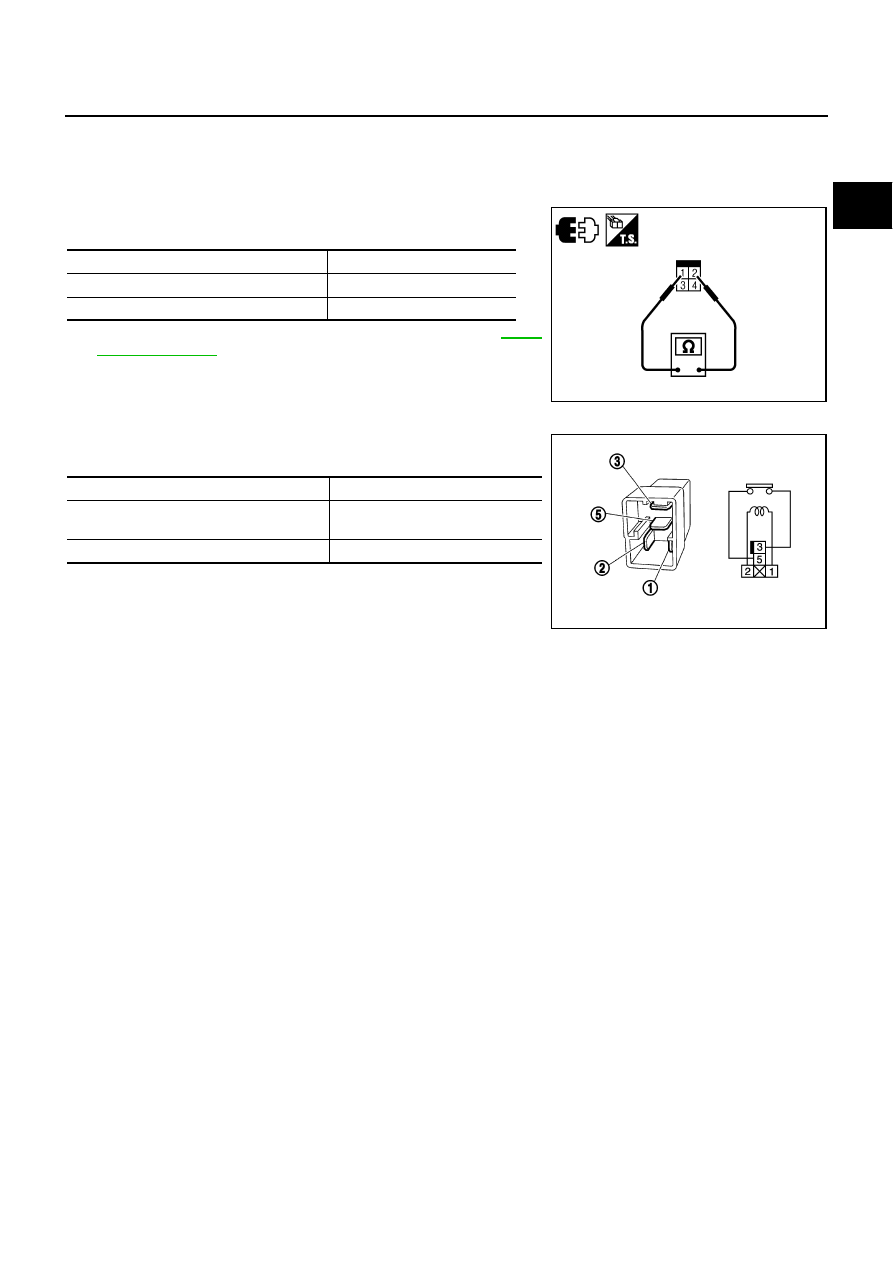
Check continuity between stop lamp switch terminals 1 and 2
under the following conditions.
4.
If NG, adjust stop lamp switch installation, refer to
ICC BRAKE HOLD RELAY
1.
Check continuity between ICC brake hold relay terminals 3 and
5 under the following conditions.
2.
If NG, replace ICC brake hold relay.
Condition
Continuity
Brake pedal: Fully released
Should not exist
Brake pedal: Slightly depressed
Should exist
PBIA9489J
Condition
Continuity
12V direct current supply between terminals
1 and 2
Should not exist
No current supply
Should exist
PBIB0098E
EC-1316
[VK45DE]
DTC P2100, P2103 THROTTLE CONTROL MOTOR RELAY
DTC P2100, P2103 THROTTLE CONTROL MOTOR RELAY
PFP:16119
Component Description
NBS005NT
Power supply for the throttle control motor is provided to the ECM via throttle control motor relay. The throttle
control motor relay is ON/OFF controlled by the ECM. When the ignition switch is turned ON, the ECM sends
an ON signal to throttle control motor relay and battery voltage is provided to the ECM. When the ignition
switch is turned OFF, the ECM sends an OFF signal to throttle control motor relay and battery voltage is not
provided to the ECM.
CONSULT-II Reference Value in Data Monitor Mode
NBS005NU
Specification data are reference values.
On Board Diagnosis Logic
NBS005NV
These self-diagnoses have the one trip detection logic.
FAIL-SAFE MODE
When the malfunction is detected, ECM enters fail-safe mode and the MlL lights up.
DTC Confirmation Procedure
NBS005NW
NOTE:
If DTC Confirmation Procedure has been previously conducted, always turn ignition switch OFF and wait at
least 10 seconds before conducting the next test.
PROCEDURE FOR DTC P2100
With CONSULT-II
1.
Turn ignition switch ON and wait at least 2 seconds.
2.
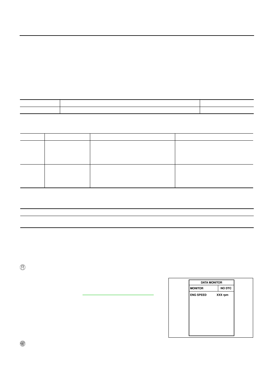
Select “DATA MONITOR””mode with CONSULT-II.
3.
Start engine and let it idle for 5 seconds.
4.
If DTC is detected, go to
EC-1319, "Diagnostic Procedure"
With GST
Follow the procedure “With CONSULT-II” above.
MONITOR ITEM
CONDITION
SPECIFICATION
THRTL RELAY
●
Ignition switch: ON
ON
DTC No.
Trouble diagnosis name
DTC detecting condition
Possible cause
P2100
2100
Throttle control motor
relay circuit open
ECM detects a voltage of power source for
throttle control motor is excessively low.
●
Harness or connectors
(Throttle control motor relay circuit is
open)
●
Throttle control motor relay
P2103
2103
Throttle control motor
relay circuit short
ECM detect the throttle control motor relay is
stuck ON.
●
Harness or connectors
(Throttle control motor relay circuit is
shorted)
●
Throttle control motor relay
Engine operating condition in fail-safe mode
ECM stops the electric throttle control actuator control, throttle valve is maintained at a fixed opening (approx. 5 degrees) by the return
spring.
SEF058Y
Нет комментариевНе стесняйтесь поделиться с нами вашим ценным мнением.
Текст