Infiniti M35/M45 Y50. Manual — part 711
DTC P2100, P2103 THROTTLE CONTROL MOTOR RELAY
EC-1317
[VK45DE]
C
D
E
F
G
H
I
J
K
L
M
A
EC
PROCEDURE FOR DTC P2103
TESTING CONDITION:
Before performing the following procedure, confirm that battery voltage is more than 8V.
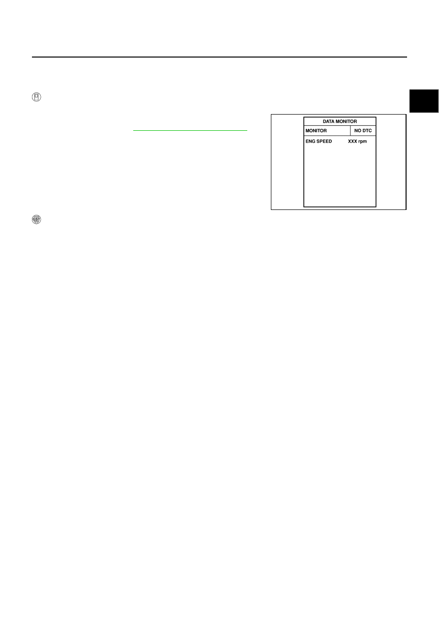
With CONSULT-II
1.
Turn ignition switch ON and wait at least 1 second.
2.
Select “DATA MONITOR” mode with CONSULT-II.
3.
EC-1319, "Diagnostic Procedure"
With GST
Follow the procedure “With CONSULT-II” above.
SEF058Y
EC-1318
[VK45DE]
DTC P2100, P2103 THROTTLE CONTROL MOTOR RELAY
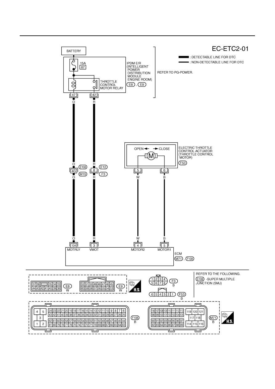
Wiring Diagram
NBS005NX
TBWT1499E
DTC P2100, P2103 THROTTLE CONTROL MOTOR RELAY
EC-1319
[VK45DE]
C
D
E
F
G
H
I
J
K
L
M
A
EC
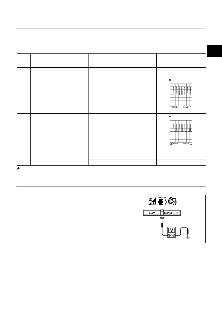
Specification data are reference values and are measured between each terminal and ground.
Pulse signal is measured by CONSULT-II.
CAUTION:
Do not use ECM ground terminals when measuring input/output voltage. Doing so may result in dam-
age to the ECM's transistor. Use a ground other than ECM terminals, such as the ground.
: Average voltage for pulse signal (Actual pulse signal can be confirmed by oscilloscope.)
Diagnostic Procedure
NBS005NY
1.
CHECK THROTTLE CONTROL MOTOR RELAY POWER SUPPLY CIRCUIT-I
1.
Turn ignition switch OFF.
2.
Check voltage between ECM terminal 104 and ground with
CONSULT-II or tester.
OK or NG
OK
>> GO TO 5.
NG
>> GO TO 2.
TER-
MINAL
NO.
WIRE
COLOR
ITEM
CONDITION
DATA (DC Voltage)
3
R
Throttle control motor relay
power supply
[Ignition switch: ON]
BATTERY VOLTAGE
(11 - 14V)
4
W
Throttle control motor
(Close)
[Ignition switch: ON]
●
Engine: Stopped
●
Selector lever: D
●
Accelerator pedal: Released
0 - 14V
5
B
Throttle control motor
(Open)
[Ignition switch: ON]
●
Engine: Stopped
●
Selector lever: D
●
Accelerator pedal: Fully depressed
0 - 14V
104
O
Throttle control motor relay
[Ignition switch: OFF]
BATTERY VOLTAGE
(11 - 14V)
[Ignition switch: ON]
0 - 1.0V
PBIB1104E
PBIB1105E
Voltage: Battery voltage
PBIB1171E
EC-1320
[VK45DE]
DTC P2100, P2103 THROTTLE CONTROL MOTOR RELAY
2.
CHECK THROTTLE CONTROL MOTOR RELAY POWER SUPPLY CIRCUIT-II
1.
Disconnect ECM harness connector.
2.
Disconnect IPDM E/R harness connector E9.
3.
Check continuity between ECM terminal 104 and IPDM E/R terminal 47.
Refer to Wiring Diagram.
4.
Also check harness for short to ground and short to power.
OK or NG
OK
>> GO TO 4.
NG
>> GO TO 3.
3.
DETECT MALFUNCTIONING PART
Check the following.
●
Harness connectors E108, M15
●
Harness for open or short between ECM and IPDM E/R
>> Repair open circuit or short to ground or short to power in harness or connectors.
4.
CHECK FUSE
1.
Disconnect 15A fuse.
2.
Check 15A fuse for blown.
OK or NG
OK
>> GO TO 8.
NG
>> Replace 15A fuse.
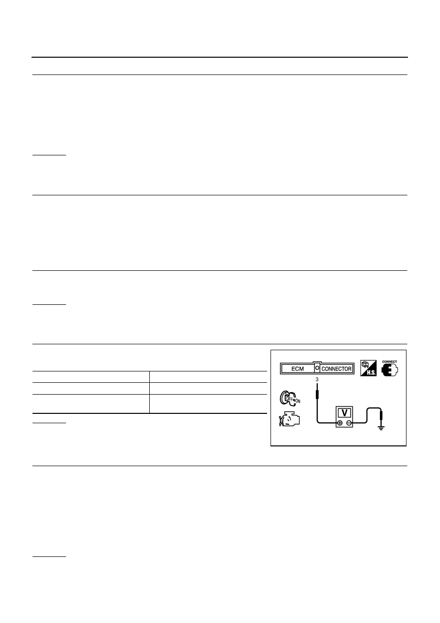
5.
CHECK THROTTLE CONTROL MOTOR RELAY INPUT SIGNAL CIRCUIT-I
1.
Check voltage between ECM terminal 3 and ground under the
following conditions with CONSULT-II or tester.
OK or NG
OK
>> GO TO 8.
NG
>> GO TO 6.
6.
CHECK THROTTLE CONTROL MOTOR RELAY INPUT SIGNAL CIRCUIT-II
1.
Turn ignition switch OFF.
2.
Disconnect ECM harness connector.
3.
Disconnect IPDM E/R harness connector E8.
4.
Check continuity between ECM terminal 3 and IPDM E/R terminal 42.
Refer to Wiring Diagram.
5.
Also check harness for short to ground and short to power.
OK or NG
OK
>> GO TO 8.
NG
>> GO TO 7.
Continuity should exist.
Ignition switch
Voltage
OFF
Approximately 0V
ON
Battery voltage
(11 - 14V)
MBIB0028E
Continuity should exist.
Нет комментариевНе стесняйтесь поделиться с нами вашим ценным мнением.
Текст