Infiniti M35/M45 Y50. Manual — part 709
DTC P1805 BRAKE SWITCH
EC-1309
[VK45DE]
C
D
E
F
G
H
I
J
K
L
M
A
EC
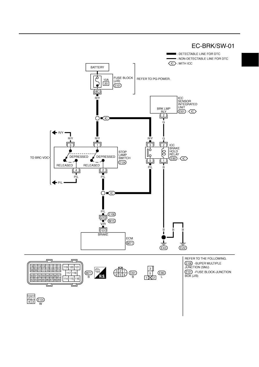
Wiring Diagram
NBS005NQ
TBWT1054E

EC-1310
[VK45DE]
DTC P1805 BRAKE SWITCH
Specification data are reference values and are measured between each terminal and ground.
CAUTION:
Do not use ECM ground terminals when measuring input/output voltage. Doing so may result in dam-
age to the ECM's transistor. Use a ground other than ECM terminals, such as the ground.
Diagnostic Procedure
NBS005NR
ICC MODELS
1.
CHECK DTC WITH ICC SENSOR INTEGRATED UNIT
Refer to
ACS-40, "TROUBLE DIAGNOSIS FOR SELF-DIAGNOSTIC ITEMS"
OK or NG
OK
>> GO TO 2.
NG
>> Repair or replace.
2.
CHECK STOP LAMP SWITCH CIRCUIT
1.
Turn ignition switch OFF.
2.
Check the stop lamp when depressing and releasing the brake pedal.
OK or NG
OK
>> GO TO 5.
NG
>> GO TO 3.
TER-
MINAL
NO.
WIRE
COLOR
ITEM
CONDITION
DATA (DC Voltage)
101
V/R
Stop lamp switch
[Ignition switch: OFF]
●
Brake pedal: Fully released
Approximately 0V
[Ignition switch: OFF]
●
Brake pedal: Slightly depressed
BATTERY VOLTAGE
(11 - 14V)
Brake pedal
Stop lamp
Fully released
Not illuminated
Slightly depressed
Illuminated
DTC P1805 BRAKE SWITCH
EC-1311
[VK45DE]
C
D
E
F
G
H
I
J
K
L
M
A
EC
3.
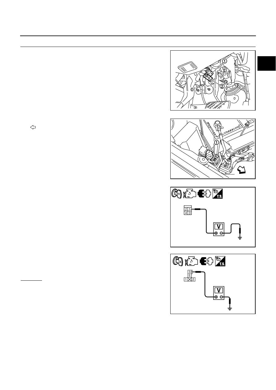
CHECK STOP LAMP SWITCH POWER SUPPLY CIRCUIT
1.
Disconnect stop lamp switch (1) harness connector.
–
ICC brake switch (2)
2.
Disconnect ICC brake hold relay (1) harness connector.
–
: Vehicle front
3.
Check voltage between stop lamp switch terminal 1 and ground
with CONSULT -II or tester.
4.
Check voltage between ICC brake hold relay terminal 3 and
ground with CONSULT -II or tester.
OK or NG
OK
>> GO TO 5.
NG
>> GO TO 4.
PBIB2705E
PBIB2699E
Voltage: Battery voltage
PBIA9488J
Voltage: Battery voltage
PBIB2740E

EC-1312
[VK45DE]
DTC P1805 BRAKE SWITCH
4.
DETECT MALFUNCTIONING PART
Check the following.
●
Fuse block (J/B) connector E101
●
10A fuse
●
Harness for open or short between battery and stop lamp switch
●
Harness for open or short between battery and ICC brake hold relay
>> Repair open circuit or short to ground or short to power in harness or connectors.
5.
CHECK STOP LAMP SWITCH INPUT SIGNAL CIRCUIT FOR OPEN AND SHORT
1.
Disconnect ECM harness connector.
2.
Check harness continuity between the following;
ECM terminal 101 and stop lamp switch terminal 2,
ECM terminal 101 and ICC brake hold relay terminal 5.
Refer to Wiring Diagram.
3.
Also check harness for short to ground and short to power.
OK or NG
OK
>> GO TO 7.
NG
>> GO TO 6.
6.
DETECT MALFUNCTIONING PART
Check the following.
●
Harness connectors E108, M15
●
Harness for open or short between ECM and stop lamp switch
●
Harness for open or short between ECM and ICC brake hold relay
>> Repair open circuit or short to ground or short to power in harness or connectors.
7.
CHECK STOP LAMP SWITCH
Refer to
EC-1315, "Component Inspection"
OK or NG
OK
>> GO TO 8.
NG
>> Replace stop lamp switch.
8.
CHECK ICC BRAKE HOLD RELAY
Refer to
EC-1315, "Component Inspection"
OK
>> GO TO 9.
NG
>> Replace ICC brake hold relay.
9.
CHECK INTERMITTENT INCIDENT
Refer to
EC-857, "TROUBLE DIAGNOSIS FOR INTERMITTENT INCIDENT"
.
>> INSPECTION END
Continuity should exist.
Нет комментариевНе стесняйтесь поделиться с нами вашим ценным мнением.
Текст