Infiniti M35/M45 Y50. Manual — part 708
DTC P1800 VIAS CONTROL SOLENOID VALVE
EC-1305
[VK45DE]
C
D
E
F
G
H
I
J
K
L
M
A
EC
2.
DETECT MALFUNCTIONING PART
Check the following.
●
Harness connectors E12, F3
●
Harness for open or short between VIAS control solenoid valve and IPDM E/R
>> Repair harness or connectors.
3.
CHECK VIAS CONTROL SOLENOID VALVE OUTPUT SIGNAL CIRCUIT FOR OPEN AND SHORT
1.
Turn ignition switch OFF.
2.
Disconnect ECM harness connector.
3.
Check harness continuity between ECM terminal 29 and VIAS control solenoid valve terminal 2.
Refer to Wiring Diagram.
4.
Also check harness for short to ground and short to power.
OK or NG
OK
>> GO TO 4.
NG
>> Repair open circuit or short to ground or short to power in harness or connectors.
4.
CHECK VIAS CONTROL SOLENOID VALVE
Refer to
EC-1305, "Component Inspection"
.
OK or NG
OK
>> GO TO 5.
NG
>> Replace VIAS control solenoid valve.
5.
CHECK INTERMITTENT INCIDENT
Refer to
EC-857, "TROUBLE DIAGNOSIS FOR INTERMITTENT INCIDENT"
>> INSPECTION END
Component Inspection
NBS005NK
VIAS CONTROL SOLENOID VALVE
With CONSULT-II
1.
Reconnect harness connectors disconnected.
2.
Turn ignition switch ON.
3.
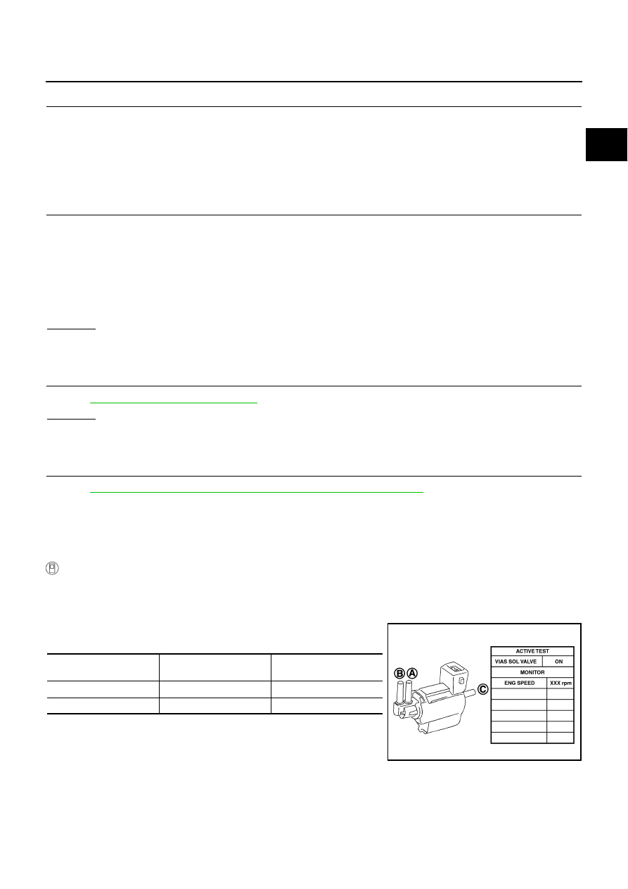
Perform “VIAS SOL VALVE” in “ACTIVE TEST” mode.
4.
Check air passage continuity and operation delay time under the
following conditions.
Operation takes less than 1 second.
Continuity should exist.
Condition
VIAS SOL VALVE
Air passage continuity
between (A) and (B)
Air passage continuity
between (A) and (C)
ON
Yes
No
OFF
No
Yes
PBIB0177E
EC-1306
[VK45DE]
DTC P1800 VIAS CONTROL SOLENOID VALVE
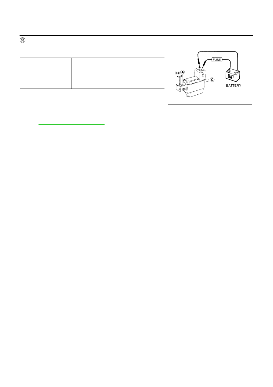
Without CONSULT-II
Check air passage continuity and operation delay time under the fol-
lowing conditions.
Operation takes less than 1 second.
Removal and Installation
NBS005NL
VIAS CONTROL SOLENOID VALVE
Refer to
Condition
Air passage continuity
between (A) and (B)
Air passage continuity
between (A) and (C)
12V direct current supply
between terminals 1 and 2
Yes
No
No supply
No
Yes
SEF313Q
DTC P1805 BRAKE SWITCH
EC-1307
[VK45DE]
C
D
E
F
G
H
I
J
K
L
M
A
EC
DTC P1805 BRAKE SWITCH
PFP:25320
Component Description
NBS005NM
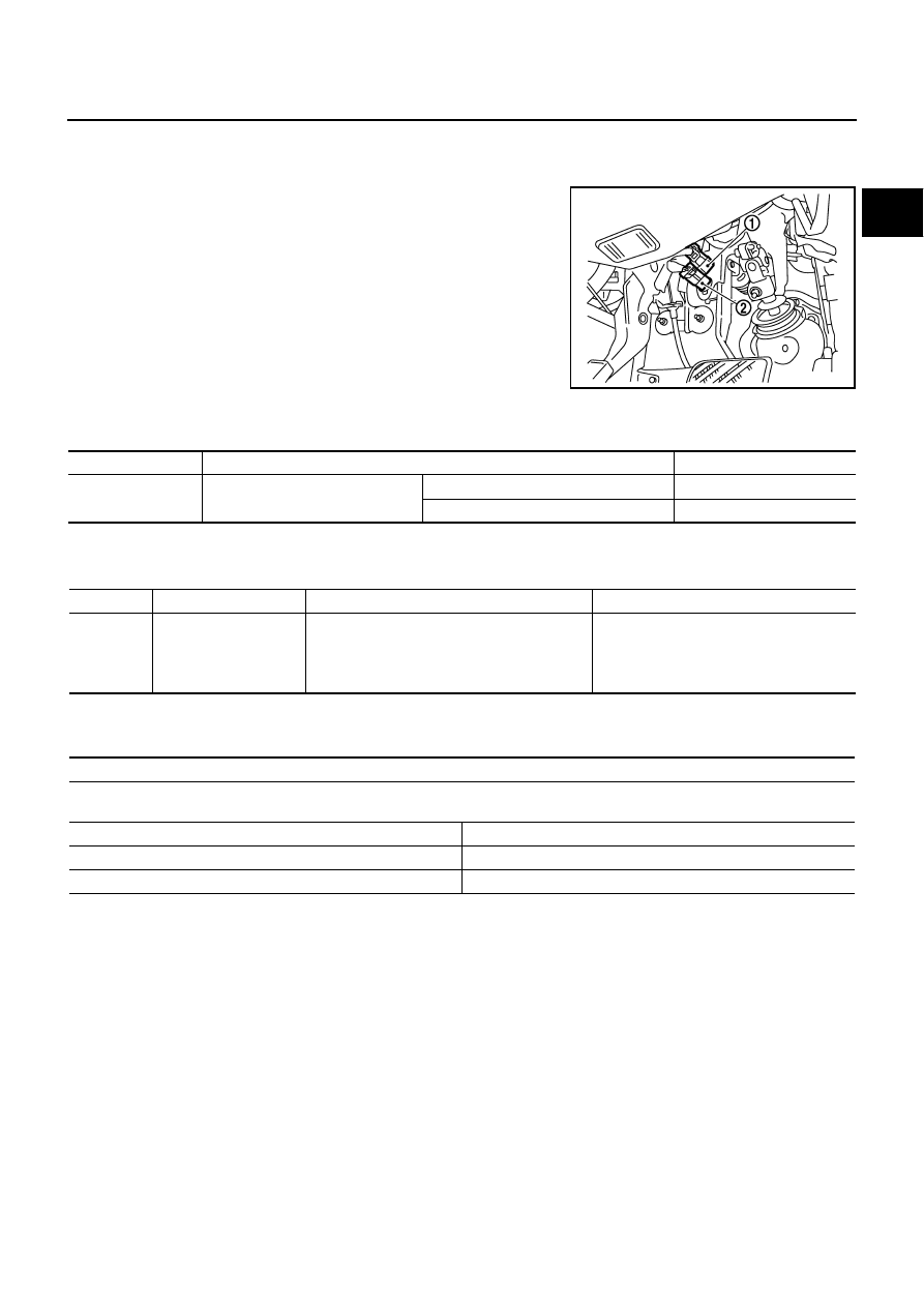
Brake switch signal is applied to the ECM through the stop lamp
switch (1) when the brake pedal is depressed. This signal is used
mainly to decrease the engine speed when the vehicle is driving.
●
ICC brake switch (models with ICC) (2)
●
ASCD brake switch (models with ASCD) (2)
CONSULT-II Reference Value in Data Monitor Mode
NBS005NN
Specification data are reference values.
On Board Diagnosis Logic
NBS005NO
The MIL will not light up for this diagnosis.
FAIL-SAFE MODE
When the malfunction is detected, ECM enters fail-safe mode.
PBIB2705E
MONITOR ITEM
CONDITION
SPECIFICATION
BRAKE SW
●
Ignition switch: ON
Brake pedal: Fully released
OFF
Brake pedal: Slightly depressed
ON
DTC No.
Trouble diagnosis name
DTC detecting condition
Possible cause
P1805
1805
Brake switch
A brake switch signal is not sent to ECM for
extremely long time while the vehicle is driving.
●
Harness or connectors
(Stop lamp switch circuit is open or
shorted.)
●
Stop lamp switch
Engine operating condition in fail-safe mode
ECM controls the electric throttle control actuator by regulating the throttle opening to a small range.
Therefore, acceleration will be poor.
Vehicle condition
Driving condition
When engine is idling
Normal
When accelerating
Poor acceleration
EC-1308
[VK45DE]
DTC P1805 BRAKE SWITCH
DTC Confirmation Procedure
NBS005NP
WITH CONSULT-II
1.
Turn ignition switch ON.
2.
Fully depress the brake pedal for at least 5 seconds.
3.
Erase the DTC with CONSULT-II.
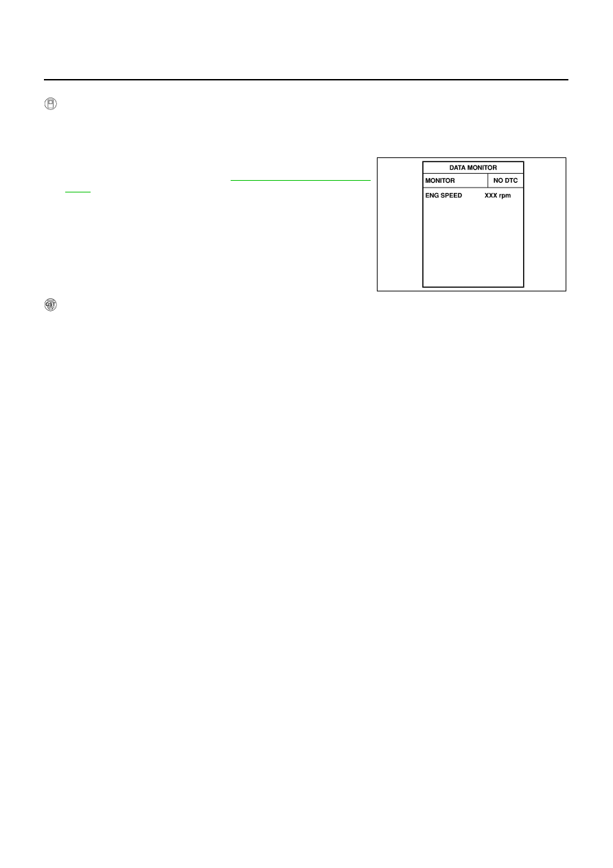
4.
Select “DATA MONITOR” mode with CONSULT-II.
5.
If 1st trip DTC is detected, go to
.
WITH GST
Follow the procedure “WITH CONSULT-II” above.
SEF058Y
Нет комментариевНе стесняйтесь поделиться с нами вашим ценным мнением.
Текст