Mitsubishi Lancer Evolution IX. Manual — part 315
KNUCKLE
REAR AXLE
27-35
KNUCKLE
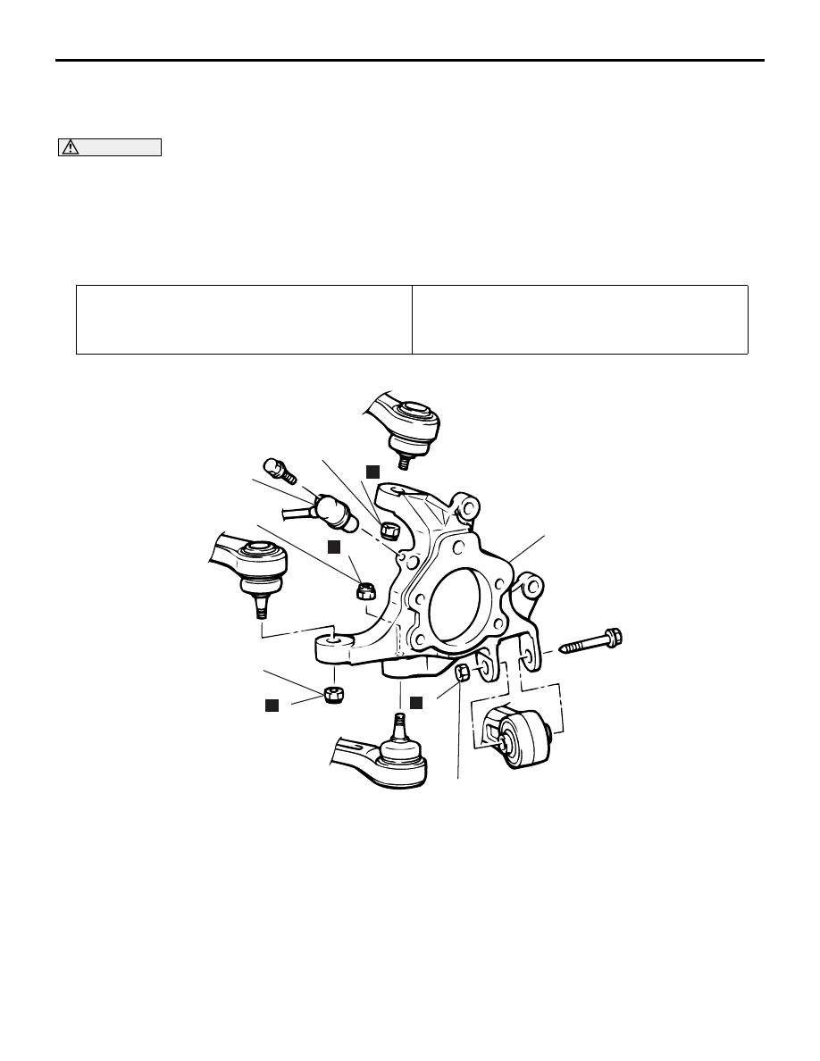
REMOVAL AND INSTALLATION
M1271003000265
CAUTION
• Be careful not to strike the pole piece at the tip of the rear ABS sensor with tools during servicing
work.
• During maintenance, take care not to contact the parts or tools to the caliper because the paint of
caliper will be scratched. And if there is brake fluid on the caliper, wipe it off quickly.
•
Pre-removal Operation
• Rear Wheel Hub Assembly Removal (Refer to
).
Post-installation Operation
• Check the ball joint dust cover for cracks or damage by
pushing it with your finger.
• Rear Wheel Hub Assembly Installation (Refer to
).
AC211951
N
4
2
1
5
6
N
3
N
N
88 ± 10 N·m*
81 ± 6 N·m*
AB
81 ± 6 N·m
81 ± 6 N·m
Removal steps
1.
Rear ABS sensor
<<
A
>>
2.
Self-locking nut (trailing arm
connection)
3.
Self-locking nut (lower arm
connection)
<<
A
>>
4.
Self-locking nut (toe control arm
connection)
<<
A
>>
5.
Self-locking nut (upper arm
connection)
6.
Knuckle
*
: Indicates parts which should be temporarily tightened, and then fully tightened with the vehicle
on the ground in the unladen condition.
Removal steps (Continued)
DRIVESHAFT ASSEMBLY
REAR AXLE
27-36
REMOVAL SERVICE POINT
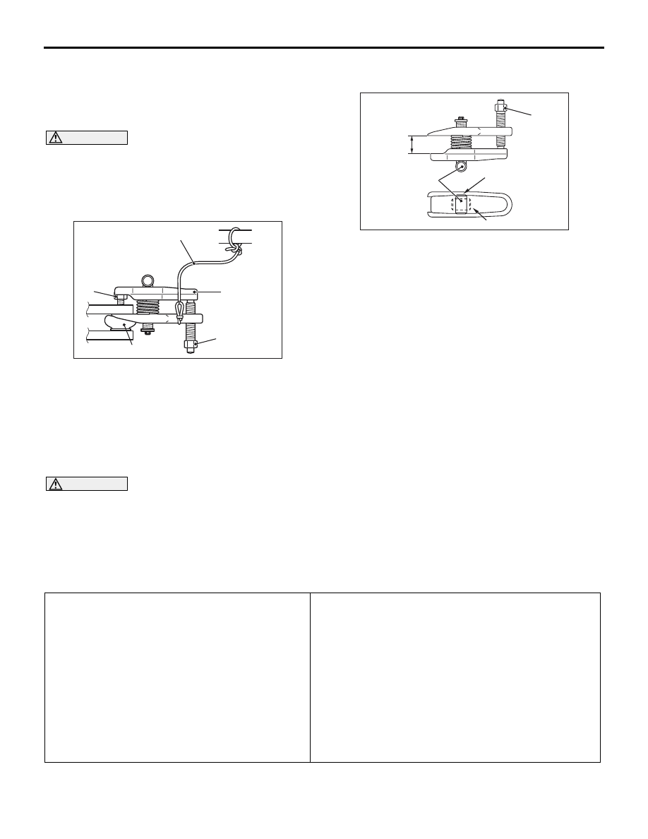
<<A>>SELF-LOCKING NUT (TRAILING
ARM, TOE CONTROL ARM AND UPPER
ARM CONNECTION) REMOVAL
CAUTION
• Do not remove the nut from ball joint. Loosen
it and use the special tool to avoid possible
damage to ball joint threads.
•
AC208247AJ
Cord
Bolt
MB991897
or
MB992011
Nut
Ball joint
Hang the special tool with cord to prevent
them from falling.
1. Install special tool ball joint remover (MB991897
or MB992011) as shown in the figure.
AC106821
Knob
Parallel
Bolt
Correct
Wrong
AD
2. After turning the bolt and knob to adjust the arms
of special tool in parallel, tighten the bolt by hand
and confirm that the arms are parallel.
NOTE: When adjusting the arms in parallel, turn
the knob so that it is at right angles to the arms.
3. Tighten the bolt with a wrench to disconnect the
ball joint and remove the self-locking nut.
INSPECTION
M1271003100154
Check the knuckle for wear or cracks.
DRIVESHAFT ASSEMBLY
REMOVAL AND INSTALLATION
M1271003300266
CAUTION
• Do not strike the ABS rotors installed to the EBJ outer race of driveshaft against other parts when
removing or installing the driveshaft. The ABS rotors will be damaged.
• Be careful not to strike the pole piece at the tip of the rear ABS sensor with tools during servicing
work.
•
Pre-installation Operation
• Centre Exhaust Pipe Removal (Refer to
GROUP15, Exhaust Pipe and Main Muffler
).
Post-installation Operation
• Check the dust cover for cracks or damage by
pushing it with your finger.
• Centre Exhaust Pipe Installation (Refer to GROUP
15, Exhaust Pipe and Main Muffler
).
• Gear Oil Filling (Refer to
).
• Parking Brake Lever Stroke Adjustment (Refer to
GROUP 36, On-vehicle Service
− Parking Brake
Lever Stroke Check and Adjustment
• Rear Wheel Alignment Check and Adjustment
(Refer to GROUP34, On-vehicle Service
−Rear
Wheel Alignment Check and Adjustment
During maintenance, take care not to contact the parts or tools to the caliper because the paint of
caliper will be scratched. And if there is brake fluid on the caliper, wipe it off quickly.
AC211952
N
N
1
4
5
225 ± 25 N·m
AB
2
3
N
6
7
13
14
8
9
11
N
12
N
10
N
88 ± 10 N·m*
81 ± 6 N·m*
81 ± 6 N·m
54 ± 5 N·m
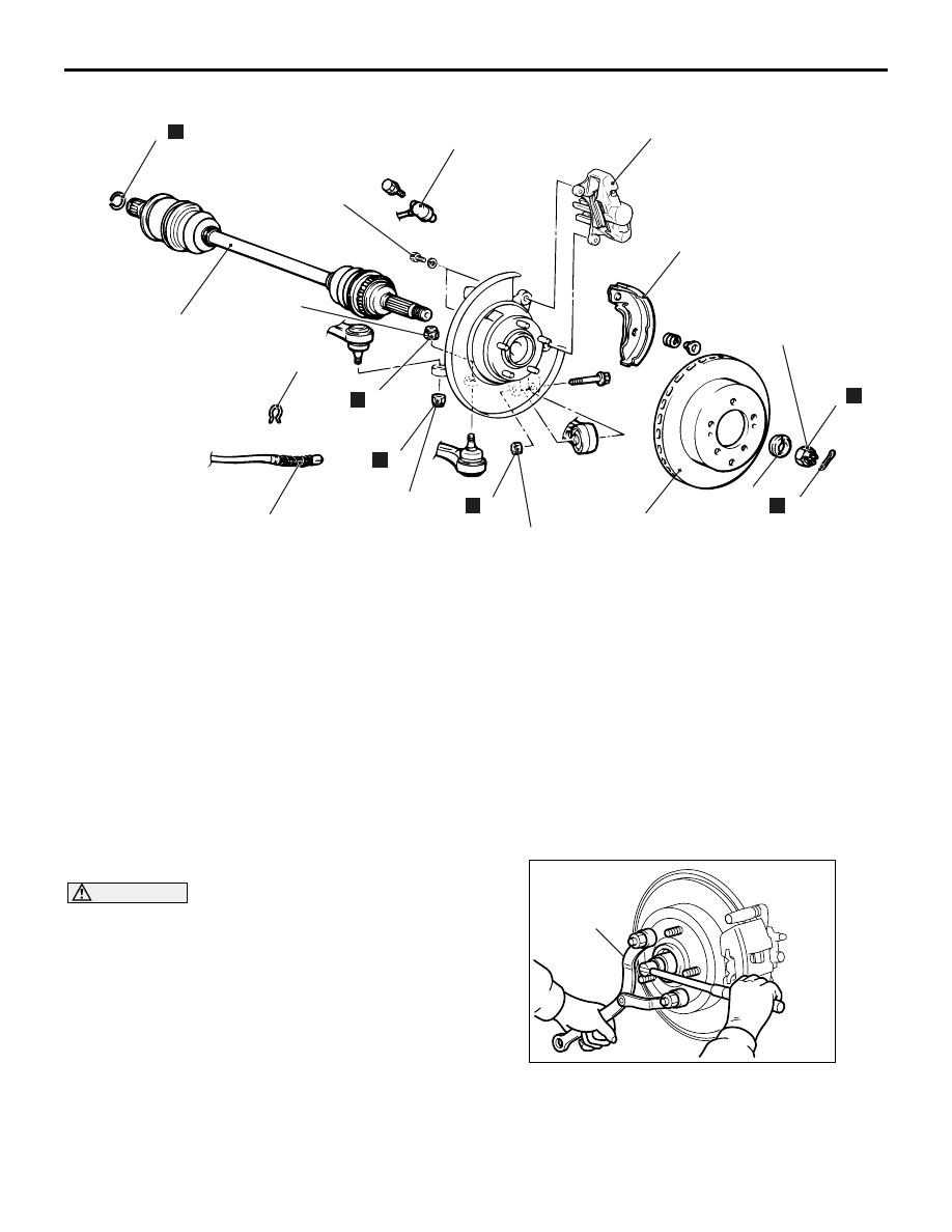
Removal steps
1. Split pin
<<
A
>> >>
B
<< 2. Driveshaft nut
>>
B
<< 3. Washer
4. Rear ABS sensor
<<
B
>>
5. Caliper assembly
6. Brake disc
7. Parking brake shoe and lining
assembly (Refer to GROUP 36,
Parking brake lining and drum
8. Clip
9. Parking brake cable connection
<<
C
>>
10. Self-locking nut (trailing arm
connection)
<<
C
>>
11. Self-locking nut (lower arm
connection)
<<
C
>>
12. Self-locking nut (toe control arm
connection)
<<
D
>> >>
A
<< 13. Driveshaft
14. Circlip
DRIVESHAFT ASSEMBLY
REAR AXLE
27-37
REMOVAL SERVICE POINTS
<<A>> DRIVESHAFT NUT REMOVAL
CAUTION
Do not apply pressure to wheel bearing by the
vehicle weight to avoid possible damage to
wheel bearing before tightening driveshaft nut
fully.
AC205988
MB990767
AB
Use special tool front hub and end yoke holder
(MB990767) to fix the hub and remove the driveshaft
nut.
Removal steps (Continued)

DRIVESHAFT ASSEMBLY
REAR AXLE
27-38
<<B>> CALIPER ASSEMBLY REMOVAL
CAUTION
During maintenance, take care not to contact the
parts or tools to the caliper because the paint of
caliper will be scratched.
Secure the removed caliper assembly with wire, etc.
<<C>>SELF-LOCKING NUT (TRAILING
ARM, LOWER ARM AND TOE CONTROL
ARM CONNECTION) REMOVAL
CAUTION
• Do not remove the nut from ball joint. Loosen
it and use the special tool to avoid possible
damage to ball joint threads.
•
AC208247AJ
Cord
Bolt
MB991897
or
MB992011
Nut
Ball joint
Hang the special tool with cord to prevent
them from falling.
1. Install special tool ball joint remover (MB991897
or MB992011) as shown in the figure.
AC106821
Knob
Parallel
Bolt
Correct
Wrong
AD
2. After turning the bolt and knob to adjust the arms
of special tool in parallel, tighten the bolt by hand
and confirm that the arms are parallel.
NOTE: When adjusting the arms in parallel, turn
the knob so that it is at right angles to the arms.
3. Tighten the bolt with a wrench to disconnect the
ball joint and remove the self-locking nut.
<<D>> DRIVESHAFT REMOVAL
AC205989
MB991354
MB990244
(Three)
MB990242
MB990767
AB
1. Use the following special tools to push out the
driveshaft from the hub.
• Puller shaft (MB990242)
• Puller bar (MB990244)
• Puller body (MB991354)
• Front hub and end yoke holder (MB990767)
CAUTION
• Do not pull on the driveshaft. Doing so will
damage the TJ. Be sure to use the pry bar.
• When pulling the driveshaft out from the dif-
ferential carrier, be careful that the spline part
of the driveshaft does not damage the oil seal.
AC102552 AE
TJ assembly
Pry bar
Differential carrier
2. Remove the driveshaft from the differential carrier
by using a pry bar.
Нет комментариевНе стесняйтесь поделиться с нами вашим ценным мнением.
Текст