Mitsubishi Lancer Evolution IX. Manual — part 313

ON-VEHICLE SERVICE
REAR AXLE
27-27
3. If the gear oil level exceeds the standard value,
add the specified gear oil up to the bottom end of
the filler plug hole.
Specified gear oil: DIA QUEEN ATF-SP III
4. Fit the filler plug and tighten it to the specified
torque.
Tightening torque: 49
± 10 N⋅m
GEAR OIL REPLACEMENT
M1272004600133
DIFFERENTIAL PART
AC310749 AC
Filler plug
Drain plug
1. Remove the drain plug to discharge the gear oil.
2. Fit the drain plug and tighten it to the specified
torque.
Tightening torque: 49
± 10 N⋅m
AC102739
Gear oil
Upper
limit
Lower
limit
6 mm
AF
3. Remove the filler plug and add the specified gear
oil up to the bottom end of the filler plug hole.
Specified gear oil: DIA QUEEN LSD gear oil
Amount to use: 0.55
± 0.02 L
4. Fit the filler plug and tighten it to the specified
torque.
Tightening torque: 49
± 10 N⋅m
TORQUE TRANSFER MECHANISM PART
AC310750 AC
Drain plug
Filler plug
1. Remove the drain plug to discharge the gear oil.
2. Fit the drain plug and tighten it to the specified
torque.
Tightening torque: 49
± 10 N⋅m
3. Remove the filler plug.
AC310751AB
Oil suction gun
(General service tool)
4. Using the oil suction gun (general service tool),
between the body and differential support arm,
apply the specified gear oil up to the under of the
filler plug hall.
Amount to use: 0.55
− 0.6 L
Specified gear oil: DIA QUEEN ATF-SP III
5. Fit the filler plug and tighten it to the specified
torque.
Tightening torque: 49
± 10 N⋅m
FLUID LEVEL CHECK
M1272004700022
1. Remove the maintenance lid located in the
luggage compartment.
2. <Not using M.U.T.-II/III>
If the vehicle has been run, leave it for 90 min. or
more in an ordinary temperature (10
− 30°C) to
allow the accumulator internal pressure to drop.
NOTE: If the ambient temperature is 10
°
C or less,
allow more time to leave the vehicle to stand idle.
3. <Using M.U.T.-II/III>

ON-VEHICLE SERVICE
REAR AXLE
27-28
CAUTION
Turn the ignition switch to the "LOCK (OFF)"
position before connecting or disconnecting the
M.U.T.-II/III.
4. Set M.U.T.-II/III to 16 pin diagnostic connector.
Turn the ignition switch to the "ON" position,
operate M.U.T.-II/III to drive (item 03: directional
valve) forcibly, release the pressure in the
accumulator.
NOTE:
.
•
To drive (oil level check mode) forcibly, turn
the directional valve of the hydraulic unit 20
turns from side to side, release the differential
automatically. Drive can also be cleared forci-
bly using the clear key of M.U.T.-II/III.
•
AC310678
If the function has been stopped by fail safe,
the hydraulic unit cannot be cleared forcibly.
5. Check that the fluid level in the oil reservoir is in
the range between MAX and MIN.
6. If the fluid level is lower than MIN, add the
specified fluid.
Specified fluid: DIA QUEEN ATF-SP III
7. Reinstall the maintenance lid.
AYC BLEEDING
M1272004800029
1. Lift up the vehicle.
CAUTION
Turn the ignition switch to the "LOCK (OFF)"
position before connecting or disconnecting the
M.U.T.-II/III.
AC100188 AN
Diagnosis connector
2. Set the M.U.T.-II/III to the 16-pin diagnosis
connector.
3. Turn the ignition switch to the "ON" position.
4. Set the steering wheel in the straight-ahead
position.
5. Operating the M.U.T.-II/III, drive the hydraulic unit
(item No.02) forcibly.
NOTE:
.
•
Drive the bleeding mode forcibly for 5 minutes,
release the operation automatically. Drive can
also be cleared forcibly using the Clear key of
M.U.T.-II/III.
•
AC310754 AB
Vinyl hose
Bleeder
screw
If the function has been stopped by fail safe,
the hydraulic unit cannot be cleared forcibly.
6. Remove the cap of the left bleeder screw on the
torque transfer differential and connect a vinyl
hose.
7. Gradually turn the steering wheel clockwise from
the straight-ahead position. At this time, loosen
the left bleeder screw and check that fluid is
discharged with air.

ON-VEHICLE SERVICE
REAR AXLE
27-29
CAUTION
While the system is being bled of air, add fluid as
necessary to ensure that it is left in the oil reser-
voir during the entire procedure.
8. After air has been completely discharged, tighten
bleeder screw and turn the steering wheel in the
straight-ahead position.
9. Repeat steps 6 and 7 two to three times until no
air bubbles are recognized in the fluid that comes
out. Then, tighten the bleeder screw to the
specified torque.
Tightening torque: 9
± 1 N⋅m
10.Perform steps 5 through 8 for the right bleeder
screw. Note, however, that the steering wheel
should be turned counterclockwise.
11.When removing the hydraulic unit, bleed the fluid
line in ACD side (Refer to GROUP 22A -
On-vehicle Service
CAUTION
If the system is not completely bled of air, the
hydraulic unit could generate noise, degrading
pump durability.
12.After the system has been completely bled of air,
check for the fluid level (Refer to
AYC OPERATION CHECK
M1272004900026
1. Lift up the vehicles.
CAUTION
Turn the ignition switch to the "LOCK (OFF)"
position before connecting or disconnecting the
M.U.T.-II/III.
AC100188 AN
Diagnosis connector
2. Set the M.U.T.-II/III to the 16-pin diagnosis
connector.
3. Start the engine.
4. Set the gear to the 2nd gear or above, operate
M.U.T.-II/III, and check from the data list (Item
No.09) that the wheel speed is within 10 km/h to
20 km/h.
NOTE:
.
•
Set the steering wheel to the neutral position.
•
When turning the steering wheel, AYC oper-
ates continually (operation sound from the
torque transfer differential), but it is not system
fault. In this case, set the steering wheel to the
neutral position, and perform the following
operations in order to stop the ACD.
•
Release the clutch.
•
Set the gear to "Neutral".
•
Stop the engine.
5. Operate the M.U.T.-II/III, drive the torque transfer
differential by the actuator test (item No.06 and
07) forcibly.
NOTE:
.
•
Drive the clutch operating mode forcibly for 1
minute, release the operation automatically.
Drive can also be cleared forcibly using the
Clear key of M.U.T.-II/III.
•
If the hydraulic unit function has been stopped
by fail-safe, the torque transfer differential can-
not be forcibly driven.
6. Operating the M.U.T.-II/III by data list (item No.07
and 08), check the condition of the wheel speed
below.
<Driving actuator test item No.06 forcibly>
The left rear wheel is faster 2 km/h than right rear
wheel.
<Driving actuator test item No.07 forcibly>
The right rear wheel is faster 2 km/h than left rear
wheel.
NOTE: If the above are not satisfied, check the oil
pressure as the system may be faulty.
OIL PRESSURE CHECK
M1272005000037
1. Lift up the vehicles.
CAUTION
Turn the ignition switch to the "LOCK (OFF)"
position before connecting or disconnecting the
M.U.T.-II/III.
AC100188 AN
Diagnosis connector
ON-VEHICLE SERVICE
REAR AXLE
27-30
2. Set the M.U.T.-II/III to the 16-pin diagnosis
connector.
3. Turn the ignition switch to "ON" position.
AC310756 AB
MD998330
MB991705
4. Disconnect the hydraulic unit and the hydraulic
unit hose assembly, connect the special tool to L
port, put the lid to R port or connect the hydraulic
unit hose assembly disconnected from L port to R
port.
• Hose adaptor (MB991705)
• Oil pressure gauge (MD998330)
5. Operating the M.U.T.-II/III, drive the hydraulic unit
forcibly (actuator test item No.02).
NOTE:
.
•
Drive the operation check mode of the clutch
left side for 1 minute, release the operation
automatically. Drive can also be cleared forci-
bly using the Clear key of M.U.T.-II/III.
•
If the function has been stopped by fail safe,
the hydraulic unit cannot be cleared forcibly.
CAUTION
While the oil pressure is checked, add fluid as
necessary to ensure that it is left in the oil reser-
voir during the entire procedure.
6. Check that the generated oil pressure of the
hydraulic unit satisfies the standard value.
Standard value: 0.9
− 1.1 MPa
7. Check the oil pressure of the clutch right side
following step 4 through 6. Connect the special
tool to R port, put the lid to L port or hydraulic unit
hose assembly disconnected from R port to L
port, use the M.U.T.-II/III to drive actuator test item
No.07 (operation check mode of clutch right side)
forcibly.
8. If the measured value exceeds the standard
value, replace the hydraulic unit.
9. Connect the hydraulic unit and the hydraulic unit
hose assembly, and connect the torque transfer
differential and hydraulic unit hose assembly,
tighten the flare nut in specified torque.
Tightening torque: 21
± 3 N⋅m
10.Supply the specified fluid up to the MAX level of
the oil reservoir, and bleed.
Specified fluid: DIA QUEEN ATF-SP III
Amount to use: 1.0 L
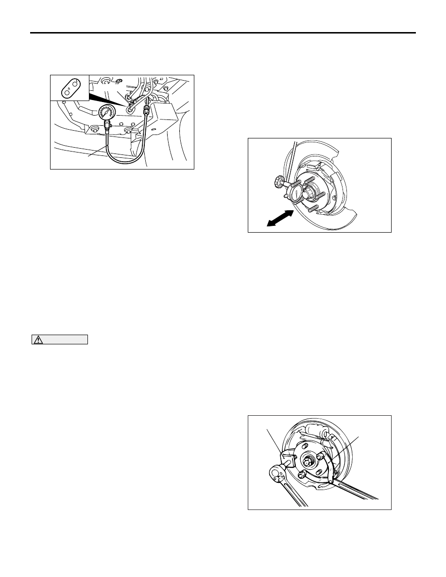
WHEEL BEARING AXIAL PLAY CHECK
M1271000900515
1. Remove the caliper assembly, and suspend the
caliper assembly with a wire and remove the
brake disc.
AC206092AC
2. Fit the dial gauge as shown in the diagram and
move the hub in the axial direction to measure the
play.
Limit: 0.05 mm
3. If the play exceeds the limit, the driveshaft nut
should be tightened to the specified torque and
check the axial play again.
Tightening torque: 225
± 25 N⋅m
4. Replace the rear hub assembly if adjustment
cannot be made to within the limit.
5. Install the brake disc and caliper assembly, and
tighten the caliper assembly mounting bolts to the
specified torque.
Tightening torque: 54
± 5 N⋅m
HUB BOLT REPLACEMENT
M1271001000195
1. Remove the brake caliper and brake disc.
AC001182
MB990767
AB
MB991618
2. Use the following special tools to remove the hub
bolts.
• Front hub and end yoke holder (MB990767)
• Hub bolt remover (MB991618)
Нет комментариевНе стесняйтесь поделиться с нами вашим ценным мнением.
Текст