Mitsubishi Lancer Evolution IX. Manual — part 351

AKX00198
Stopper
Pinion gap
Pinion
AC
STARTING SYSTEM
ENGINE ELECTRICAL
16-21
4. Check the pinion-to-stopper clearance (pinion
gap) with a feeler gauge.
Standard value: 0.5
− 2.0 mm
AKX00199
5. If the pinion gap is out of specification, adjust by
adding or removing gasket(s) between the
magnetic switch and front bracket.
MAGNETIC SWITCH PULL-IN TEST
AKX01243
B
M
S
Battery
Starter
motor
Wire
AF
1. Disconnect the field coil wire from the M-terminal
of the magnetic switch.
CAUTION
This test must be performed quickly (in less than
10 seconds) to prevent the coil from burning.
2. Connect a 12-volt battery between the S-terminal
and M-terminal.
3. If the pinion moves out, the pull-in coil is good. If it
doesn't, replace the magnetic switch.
MAGNETIC SWITCH HOLD-IN TEST
AKX01245
B
M
S
Battery
Starter
motor
Wire
AF
1. Disconnect the field coil wire from the M-terminal
of the magnetic switch.
CAUTION
This test must be performed quickly (in less than
10 seconds) to prevent the coil from burning.
2. Connect a 12-volt battery between the S-terminal
and body.
3. Manually pull out the pinion as far as the pinion
stopper position.
4. If the pinion remains out, everything is in order. If
the pinion moves in, the hold-in circuit is open.
Replace the magnetic switch.
FREE RUNNING TEST
AKX01247
S
M
B
Ammeter
Carbon-pile
rheostat
Battery
Starter
motor
Voltmeter
AF
A
V
1. Place the starter motor in a vise equipped with
soft jaws and connect a fully-charged 12-volt
battery to the starter motor as follows:
2. Connect a test ammeter (100-ampere scale) and
carbon pile rheostat in series between the positive
battery terminal and starter motor terminal.
3. Connect a voltmeter (15-volt scale) across the
starter motor.
4. Rotate the rheostat to full-resistance position.
5. Connect the battery cable from the negative
battery terminal to the starter motor body.
6. Adjust the rheostat until the battery positive
voltage shown on the voltmeter is 11 V.
STARTING SYSTEM
ENGINE ELECTRICAL
16-22
7. Confirm that the maximum amperage is within the
specifications and that the starter motor turns
smoothly and freely.
Current: maximum 95 Amps
MAGNETIC SWITCH RETURN TEST
AKX01249
B
M
S
Battery
Starter
motor
Wire
AF
1. Disconnect the field coil wire from the M-terminal
of the magnetic switch.
CAUTION
This test must be performed quickly (in less than
10 seconds) to prevent the coil from burning.
2. Connect a 12-volt battery between the M-terminal
and body.
WARNING
Be careful not to get your fingers caught
when pulling out the pinion.
3. Pull the pinion out and release. If the pinion
quickly returns to its original position, everything is
operating properly. If it doesn't, replace the
magnetic switch.
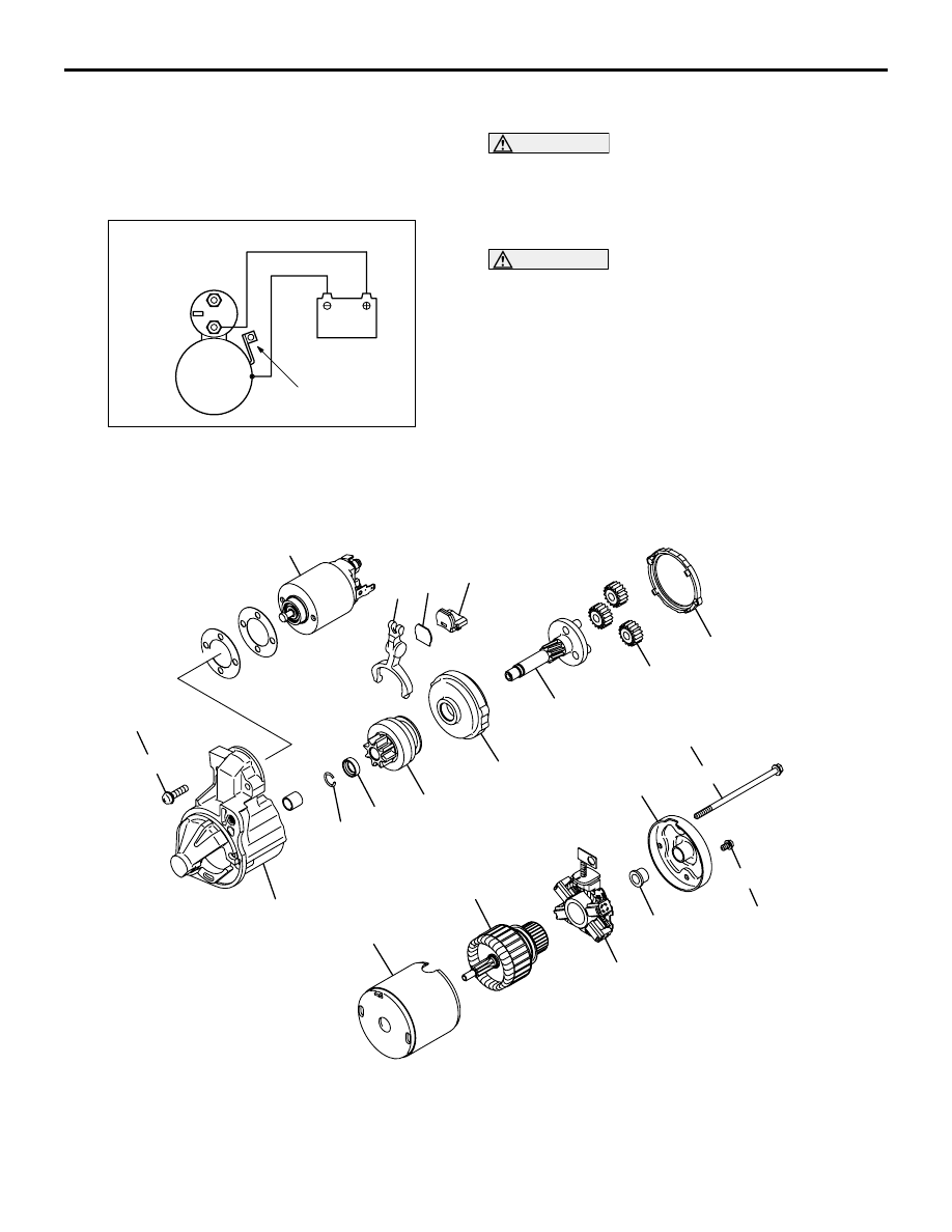
DISASSEMBLY AND REASSEMBLY
M1162001200246
AK304626AB
2
16
17
18
19
15
13
12
21
4
14
11
1
5
6
8
7
9
10
3
5.8 ± 1.6 N·m
5.8 ± 1.6 N·m
3.4 ± 1.0 N·m
Disassembly steps
1. Screw
<<
A
>>
2. Magnetic switch
3. Screw
4. Bolt
5. Rear bracket
6. Brush holder
7. Rear bearing
8. Armature
9. Yoke assembly
10. Packing A
11. Packing B
12. Plate
13. Planetary gear
14. Lever
<<
B
>> >>
A
<< 15. Snap ring
<<
B
>> >>
A
<< 16. Stop ring
17. Overrunning clutch
18. Internal gear
19. Planetary gear shaft
20. Front bracket
STARTING SYSTEM
ENGINE ELECTRICAL
16-23
DISASSEMBLY SERVICE POINTS
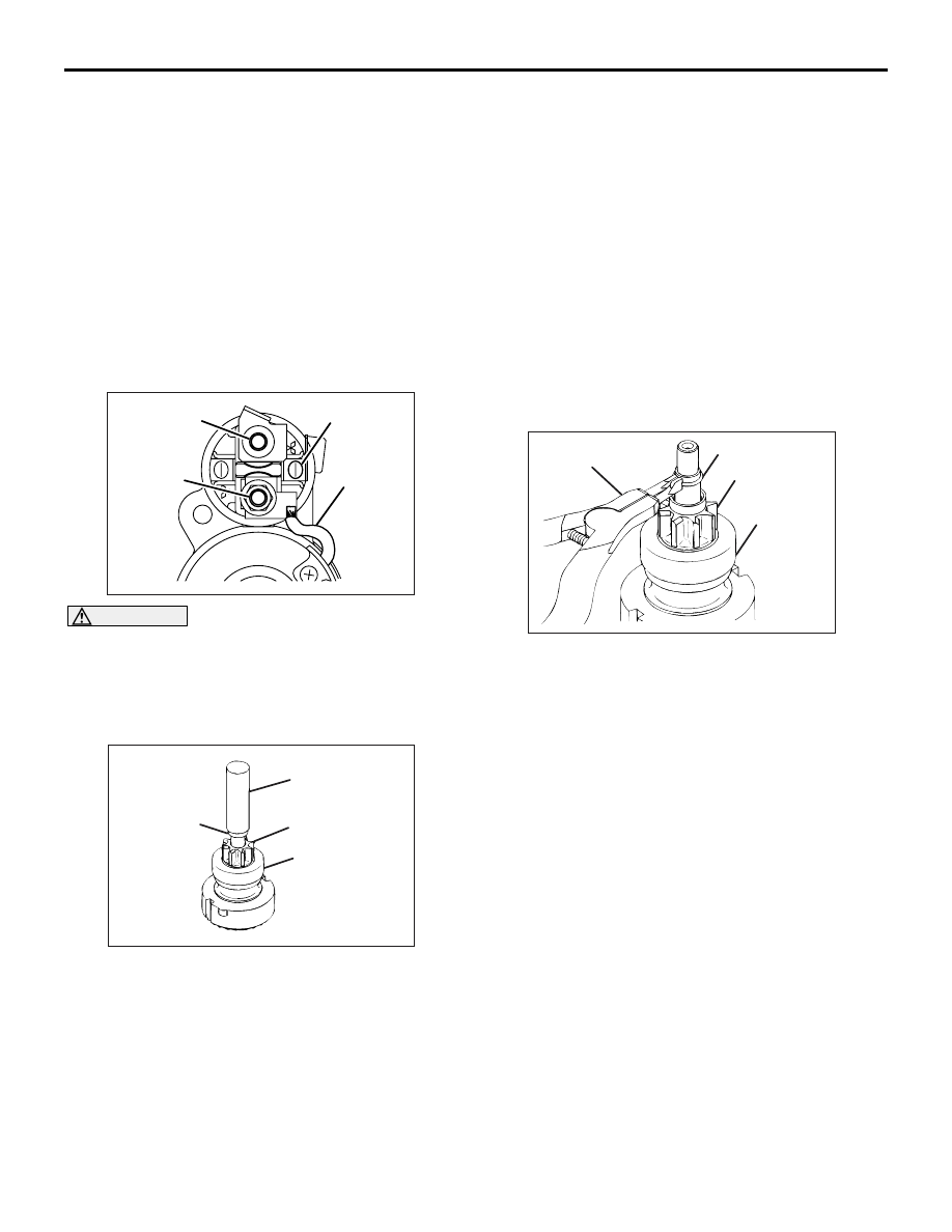
<<A>> MAGNETIC SWITCH REMOVAL
AK202890
B terminal
M terminal
S terminal
Field coil
lead
AB
CAUTION
Do not clamp the yoke assembly with a vise.
Disconnect the lead from the M terminal of the mag-
netic switch.
<<B>> SNAP RING/STOP RING REMOVAL
AK202790
Socket wrench
Stop ring
Pinion Gear
Overrunning
clutch
AB
1. Apply a long socket wrench of an appropriate size
to the stop ring and strike the wrench to drive out
the stop ring toward the pinion gear side.
AK202791
Snap ring
pliers
Snap ring
Pinion gear
Overrunning
clutch
AB
2. Remove the snap ring with snap ring pliers, then
remove the stop ring and overrunning clutch.
STARTER MOTOR PARTS CLEANING
Never clean in a solvent such starter motor parts as
the magnetic switch, brush holder, and armature.
If they are soaked in a solvent, their insulation
could be impaired. When these parts require
cleaning, wipe off contamination with cloth.
1. Never soak the drive unit in a solvent. If it is
washed in a solvent, the grease having been
packed in the overrunning clutch at the factory will
be washed out. Wipe the drive unit with cloth if it
requires cleaning.
Disassembly steps (Continued)

STARTING SYSTEM
ENGINE ELECTRICAL
16-24
REASSEMBLY SERVICE POINTS
>>A<< STOP RING/SNAP RING INSTAL-
LATION
AK202911
Overrunning
clutch
Stop ring
Snap ring
Stop ring
AB
Use a suitable puller to pull the stop ring until it gets
over the snap ring.
INSPECTION
M1162001300180
COMMUTATOR
AK202712
1. Support the armature with a pair of V block and
turn it to measure the runout of the surface not
rubbed by the brushes using a dial gauge.
Standard value: 0.05 mm or less
Limit: 0.1 mm
AK202715
2. Measure the diameter of the commutator.
Standard value: 29.4 mm
Limit: 28.8 mm
AK202711
Segment
Undercut
Mica
AB
3. Measure the depth of the undercut between
segments.
Standard value: 0.5 mm
Limit: 0.2 mm
BRUSH HOLDER
AK202897
Push the brush into the brush holder to make sure
that the spring is working on the brush.
If the spring is not working, replace the brush holder.
OVERRUNNING CLUTCH
AK202710
Free
Lock
AB
1. Make sure that the pinion cannot be turned
counterclockwise and can be turned clockwise
freely.
2. Check the pinion for abnormal ware and damage.
Нет комментариевНе стесняйтесь поделиться с нами вашим ценным мнением.
Текст