Mitsubishi Lancer Evolution IX. Manual — part 352

STARTING SYSTEM
ENGINE ELECTRICAL
16-25
BRUSHES
AK202846
Brush
height
AB
1. Check the commutator contacting surface of each
brush for abnormal roughness. Also check the
height of the brush. Replace the brush holder if
the height is lower than the limit.
Limit: 7.0 mm
2. When the contact surface of the brush is rectified
or the brush holder is replaced, recondition the
contact surface with sandpaper wrapped around
the commutator.
ARMATURE COIL
1. Check the armature coil for short circuit as
follows:
AK202733
Growler
AB
2. Set the armature in a growler.
CAUTION
Clean the surface of the armature thoroughly
before performing the test.
3. While holding a thin strip of iron against the
armature in parallel with its axis, turn the armature
slowly. The armature is normal if the iron strip is
not attracted to the armature or it does not vibrate.
AK202734
4. Check the insulation between commutator
segments and armature coils. The armature coils
are properly insulated if no continuity is present.
AK202713
5. Check continuity between a segment and another.
There is no open circuit in the tested coil if there is
continuity.
MAGNETIC SWITCH
AK202891
A
M terminal
AB
1. Coil open circuit test
• Check that there is continuity between the M ter-
minal and body A.
• If there is no continuity, replace the magnetic
switch.
AK202892
M terminal
B terminal
AB
IGNITION SYSTEM
ENGINE ELECTRICAL
16-26
2. Contact fusion check
• Check that there is no continuity between the B
terminal and M terminal.
•
AK202893
M terminal
B terminal
AB
If there is continuity, replace the magnetic switch.
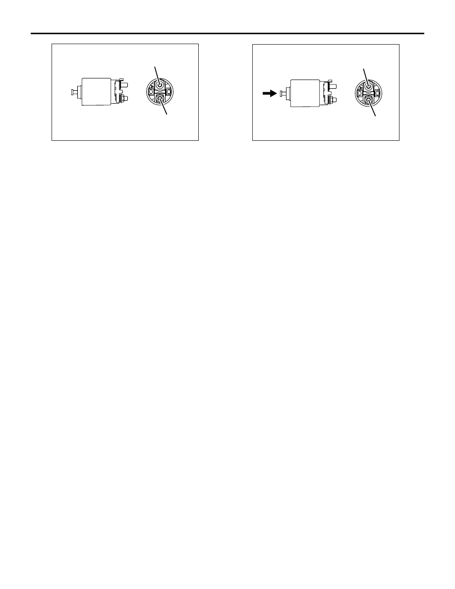
3. Switch contact check
• Push the indicated end of the magnetic switch
with a strong force to close the internal contacts.
Without releasing the switch end, check that
there is continuity between the B terminal and M
terminal.
• If there is no continuity, replace the magnetic
switch.
IGNITION SYSTEM
GENERAL INFORMATION
M1163000100614
This system is equipped with two ignition coils (A and
B) with built-in power transistors for the No. 1 and
No. 4 cylinders and the No. 2 and No. 3 cylinders
respectively.
Interruption of the primary current flowing in the pri-
mary side of ignition coil A generates a high voltage
in the secondary side of ignition coil A. The high volt-
age thus generated is applied to the spark plugs of
No. 1 and No. 4 cylinders to generate sparks. At the
time that the sparks are generated at both spark
plugs, if one cylinder is at the compression stroke,
the other cylinder is at the exhaust stroke, so that
ignition of the compressed air/fuel mixture occurs
only for the cylinder which is at the compression
stroke.
In the same way, when the primary current flowing in
ignition coil B is interrupted, the high voltage thus
generated is applied to the spark plugs of No. 2 and
No. 3 cylinders.
The engine-ECU turns the two power transistors
inside the ignition coils alternately on and off. This
causes the primary currents in the ignition coils to be
alternately interrupted and allowed to flow to fire the
cylinders in the order 1-3-4-2.
The engine-ECU determines which ignition coil
should be controlled by means of the signals from
the camshaft position sensor which is incorporated in
the camshaft and from the crank angle sensor which
is incorporated in the crankshaft. It also detects the
crankshaft position in order to provide ignition at the
most appropriate timing in response to the engine
operation conditions. It also detects the crankshaft
position in order to provide ignition at the most
appropriate timing in response to the engine opera-
tion conditions.
When the engine is cold or operated at high alti-
tudes, the ignition timing is slightly advanced to pro-
vide optimum performance.

IGNITION SYSTEM
ENGINE ELECTRICAL
16-27
SYSTEM DIAGRAM
AK101074
Air flow sensor
Intake air temperature
sensor
Engine coolant
temperature sensor
Camshaft position
sensor
Crank angle sensor
Barometric pressure
sensor
Detonation sensor
Vehicle speed
sensor
Ignition switch-ST
Engine-ECU
Ignition coil B
Cylinder No.
2
3
4
AH
1
Spark plug
Ignition coil A
Ignition
switch
Battery
IGNITION COIL SPECIFICATION
Item
Specification
Type
Molded 2-coil
SPARK PLUG SPECIFICATIONS
Item
Specifications
NGK
ILFR7H
SERVICE SPECIFICATIONS
M1163000300403
IGNITION COIL
Item
Standard value
Secondary coil resistance k
Ω
8.5
− 11.5
SPARK PLUG
Item
Standard value
Limit
Spark plug gap mm
0.5
− 0.6
0.75
SPARK PLUG CABLE
Item
Standard value
Limit
Resistance k
Ω
−
Maximum 19

IGNITION SYSTEM
ENGINE ELECTRICAL
16-28
SPECIAL TOOL
M1163000600288
Tool
Number
Name
Use
MD998773
Detonation sensor
wrench
Detonation sensor
removal and installation
ON-VEHICLE SERVICE
IGNITION COIL (WITH BUILT-IN POWER TRANSISTOR) CHECK
M1163001200614
Check by the following procedure, and replace if
there is a malfunction.
SECONDARY COIL RESISTANCE CHECK
AKX01264
Measure the resistance between the high-voltage
terminals of the ignition coil.
Standard value: 8.5
− 11.5 kΩ
PRIMARY COIL AND POWER TRANSIS-
TOR CONTINUITY CHECK
NOTE:
.
•
AK501917
1 2 3
AB
1.5 V
+
–
An analogue-type circuit tester should be used.
•
Connect the negative (-) prove of the circuit tester
to terminal No. 1.
CAUTION
This test must be performed quickly (in less than
10 seconds) to prevent coil from burning and
power transistor from breakage.
1.5 V power supply
between 2
− 3
Continuity between 1
−
2
When current is flowing
Continuity
When current is not
flowing
No continuity
IGNITION COIL RELAY CHECK <RH
DRIVE VEHICLES>
M1163006500029
CAUTION
The top and bottom of the ignition coil relay are
difficult to identify. The triangle mark on the relay
surface should be uppermost.
AC311402AB
1. Removal the ignition coil relay.
Нет комментариевНе стесняйтесь поделиться с нами вашим ценным мнением.
Текст