Mitsubishi Lancer Evolution IX. Manual — part 349

AC406359
1
7
6
4
8
5
10
9
11
AB
3
9.0 ± 1.0 N·m
12
13
14
15
16
17
18
11 ± 1 N·m
22 ± 4 N·m
24 ± 4 N·m
44 ± 10 N·m
20 ± 2 N·m
5.0 ± 1.0 N·m
8.8 ± 1.0 N·m
13 ± 1 N·m
N
9.0 ± 1.0 N·m
2
5.0 ± 1.0 N·m
(Engine oil)
Removal steps
1.
Fuel injector connectors
2.
Accelerator cable connection
<<
A
>>
3.
Fuel injector, delivery pipe, fuel
return pipe and fuel pressure
regulator assembly
4.
Insulators
5.
Insulators
6.
Fuel pressure solenoid valve
connector
7.
Fuel pressure solenoid valve
8.
Detonation sensor connector
9.
Purge control solenoid valve
connector
10. Purge control solenoid valve
11. Oil level gauge and guide assembly
12. O-ring
<<
B
>>
13. Drive belt
14. Alternator connector and terminal
•
Engine front mounting bracket
(Refer to GROUP 32, Engine
Mounting
).
<<
C
>>
15. Alternator
16. Water pump pulley
17. Crank angle sensor connector
18. Alternator bracket
CHARGING SYSTEM
ENGINE ELECTRICAL
16-13
Removal steps (Continued)

CHARGING SYSTEM
ENGINE ELECTRICAL
16-14
REMOVAL SERVICE POINTS
<<A>> FUEL INJECTOR, DELIVERY PIPE,
FUEL RETURN PIPE AND FUEL PRES-
SURE REGULATOR ASSEMBLY
REMOVAL
After loosening the delivery pipe mounting bolts,
move the fuel injector, delivery pipe, fuel return pipe
and the fuel pressure regulator as an assembly aside
in order to make room for the alternator removal.
<<B>> DRIVE BELT REMOVAL
The following operations will be needed due to the
introduction of the serpentine drive system with the
drive belt auto-tensioner.
AC210996 AB
Auto-
tensioner
Hole A
Hole B
1. Securely insert the spindle handle or ratchet
handle with a 12.7 mm insertion angle into the jig
hole of the auto-tensioner.
2. Rotate the auto-tensioner anti-clockwise and align
hole A with hole B.
CAUTION
To reuse the drive belt, draw an arrow indicating
the rotating direction (clockwise) on the back of
the belt using chalk, etc.
AC210998AB
L-shaped
hexagon
wrench
Auto-
tensioner
3. Insert an L-shaped hexagon wrench, etc. into the
hole to fix and then remove the drive belt.
<<C>> ALTERNATOR REMOVAL
Raise the engine with a floor jack and remove the
alternator upward from the engine room.
CHARGING SYSTEM
ENGINE ELECTRICAL
16-15
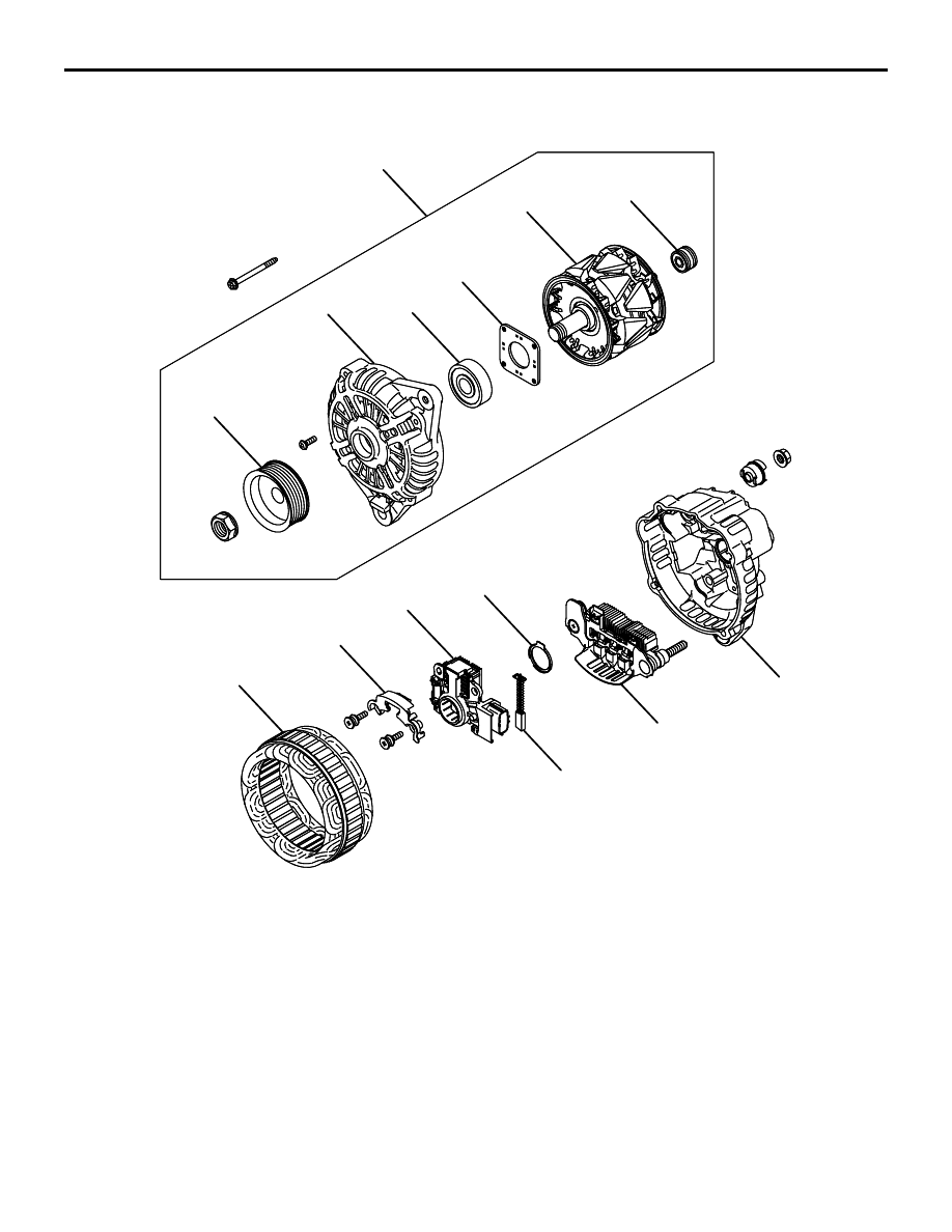
DISASSEMBLY AND REASSEMBLY
M1161001600199
AK202845
1
2
3
4
5
6
7
8
9
10
11
12
13
14
AB
Disassembly steps
<<
A>>
1. Front bracket assembly
<<
B>>
2. Alternator pulley
>>B
<< 3. Rotor
4. Rear bearing
5. Bearing retainer
6. Front bearing
7. Front bracket
<<
C>>
8. Stator
9. Plate
<<
C>> >>A
<< 10. Regulator assembly
11. Brush
12. Rubber packing
13. Rectifier
14. Rear bracket
Disassembly steps (Continued)

CHARGING SYSTEM
ENGINE ELECTRICAL
16-16
DISASSEMBLY SERVICE POINTS
<<A>> FRONT BRACKET ASSEMBLY
REMOVAL
AK202718
CAUTION
Do not insert the screwdriver blades too deep.
Doing so could damage the stator coil.
Insert the blades of screwdrivers between the front
bracket assembly and stator core, and pry and sepa-
rate them with the screwdrivers.
<<B>> ALTERNATOR PULLEY REMOVAL
AK202714
CAUTION
Perform operation carefully not to damage the
rotor.
Clamp the rotor in a vise with the pulley facing up to
remove the pulley.
<<C>> STATOR / REGULATOR
ASSEMBLY REMOVAL
AK202778
Solder
Solder
Rectifier
assembly
AB
CAUTION
• Use a 180 − 250 W soldering iron, and finish
unsoldering within four seconds. Diodes will
be damaged by heat if unsoldering time is too
long.
• Avoid applying undue force to the diode
leads.
1. Unsolder the stator leads from the main diode of
the rectifier assembly when the stator is removed.
2. When removing the rectifier assembly from the
regulator assembly, undo the soldered points on
the rectifier assembly.
REASSEMBLY SERVICE POINTS
>>A<< REGULATOR ASSEMBLY INSTAL-
LATION
AK202779
Wire
AB
AK202830
Rear bracket
Brush
Wire
AB
After installing the regulator assembly, insert a piece
of wire through the hole in the rear bracket while
pressing the brush to keep the brush against move-
ment.
NOTE: Holding the brush with the wire facilities
installation of the rotor.
Нет комментариевНе стесняйтесь поделиться с нами вашим ценным мнением.
Текст