Mitsubishi Montero (1991+). Manual — part 70
gear. Securely stake pin in 2 places. Ensure adhesive is removed from
ring gear mounting bolts and gear mounting surface. Clean internal
threads with tap.
5) Ensure alignment marks on differential case and ring gear
are aligned. Apply Loctite 271 to bolts and install ring gear on
differential case. Tighten bolts in diagonal sequence to
specification. See TORQUE SPECIFICATIONS table at the end of this
article.
CASE ASSEMBLY (LIMITED SLIP)
1) Assemble 2 friction discs and 2 friction plates; assemble
plate, disc, plate and disc. Measure assembly thickness. Assemble
discs and plates to give standard difference of .002" (.05 mm) between
the 2 sides.
2) Assemble spring plates and spring discs with one on each
side. Measure assembly thickness. Assemble disc and plates to obtain
minimum difference in thickness between each assembly.
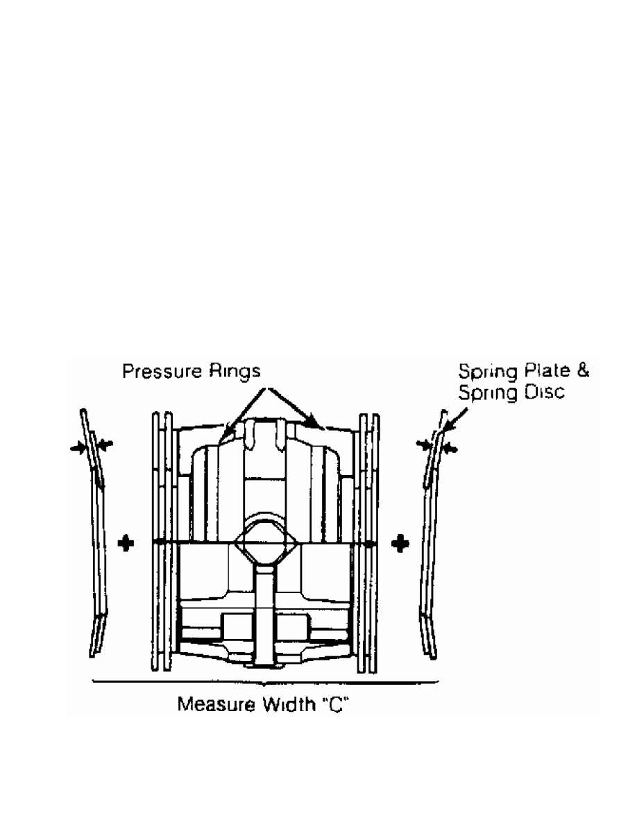
3) Assemble clutch assemblies, pressure rings, pinion gears,
side gears and pinion shaft. Measure overall width of assembly plus
spring plates and spring discs. This measurement is "C". See Fig. 6.
Fig. 6: Measuring Clutch Assembly Width
Courtesy of Chrysler Motors.
4) Determine depth "D" of differential case, using formula
"D"="E"+"F"-"G" or "D"="E"+"H"-"F"-"G" . See Fig. 7. Subtract
measurement "C" from measurement "D" to determine spring plate-to-case
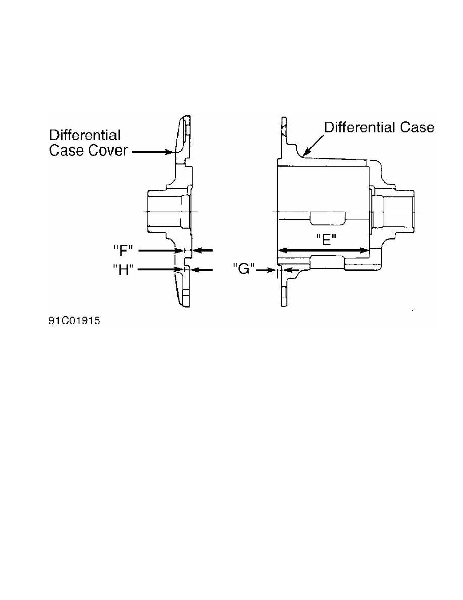
clearance. Adjust spring disc thickness to obtain proper spring plate-
to-case clearance. Correct clearance is .0024-.0079" (.060-.200 mm).
Fig. 7: Measuring Limited Slip Case Depth (Montero 3.0L & Pickup)
Courtesy of Chrysler Motors.
CAUTION: DO NOT interchange clutch components for right and left
sides. Mark clutch components for location.
5) Remove spring plates, spring discs, friction plates and
friction disc from pressure rings. Mark components for location.
Install thrust washers on each end of pressure rings. See Fig. 8.
6) Measure distance from end of thrust washer to rear face of
pressure ring. Select proper thickness thrust washers to obtain a .
002" (.05 mm) or less difference between measurements.
7) Once correct thrust washers are determined, install thrust
washers on pressure rings. Squeeze pressure rings together and measure
width from end of thrust washer to remaining thrust washer. This is
dimension "H". See Fig. 8.
8) Determine distance between thrust washer surfaces when
differential case is assembled. This is dimension "I"
("I"="J"+"K"+"L"). See Fig. 8. Dimension "J" is the same as dimension
"D" in step 4).
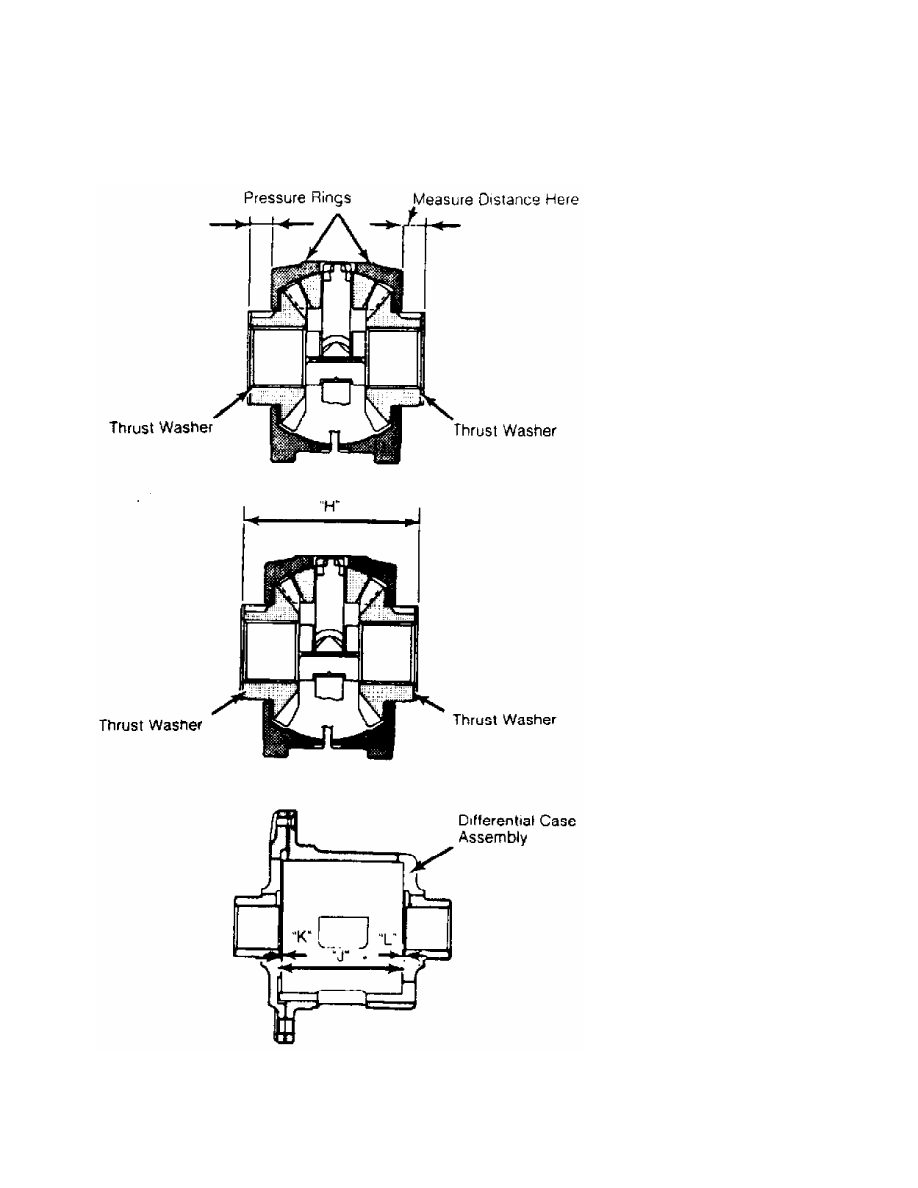
Fig. 8: Measuring Thrust Washer Clearance
Courtesy of Chrysler Motors.
9) Subtract dimension "H" from dimension "I". See Fig. 8.
This is the clearance between thrust washer and differential case.

Thrust washer must be changed to obtain correct specification. Correct
clearance is .002-.008" (.05-.20 mm).
10) Select thrust washers to obtain correct clearance from
pressure ring face and end of thrust washer surface. Thrust washers
are available in 3 sizes.
11) Apply gear oil and friction modifier to all components.
Install components in differential case. Ensure assembly order and
direction of clutch components are correct. See Fig. 9.
Fig. 9: Limited Slip Differential Assembly
Courtesy of Chrysler Motors.
12) Install differential case cover with reference marks
aligned. Tighten screws to specification in several steps. See TORQUE
SPECIFICATIONS table at end of article. Ensure cases contact each
other completely when fully assembled. Check for incorrect clutch
assembly if gap exists.
13) Using Clutch Plate Preload Tool (MB990988), Shaft
(MB990989) and torque wrench, measure starting torque. Slightly rotate
unit before measuring starting torque. See Fig. 10.
Нет комментариевНе стесняйтесь поделиться с нами вашим ценным мнением.
Текст