Mitsubishi Montero (1991+). Manual — part 69
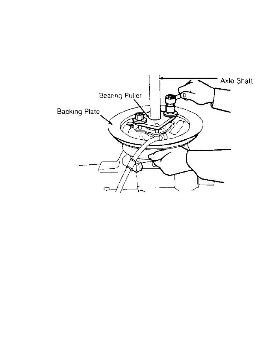
Fig. 2: Removing Bearing Case from Axle Shaft
Courtesy of Chrysler Motors.
Inspection
Inspect bearings for roughness, pitting or damage. Inspect
axle shaft for damaged splines or flange. Inspect bearing case for
cracks or damage. Measure axle shaft O.D. in bearing area. Correct O.
D. is 1.57" (39.8 mm). Axle shaft must be replaced if O.D. is not to
specification.
Reassembly
1) Apply grease to outer surface of bearing outer race and
oil seal.Install outer race in bearing case. Install oil seal in
bearing case until it is even with bearing case surface. Apply grease
to bearing rollers. Install brake assembly, bearing case and bearing
onto axle shaft.
2) Apply grease to bearing rollers. Press inner bearing onto
axle shaft. Pack bearing case with grease. Coat lock nut threads with
grease. Install washer, NEW lock washer and lock nut. Lock nut must be
installed with chamfered edge toward axle shaft flange. Tighten lock
nut to specification. See TORQUE SPECIFICATIONS table at end of
article. Bend tab on lock washer into groove on lock nut.
DIFFERENTIAL
NOTE: Check pinion and side gear backlash, ring gear backlash and
ring gear runout before disassembly.
Disassembly
1) Remove differential carrier from axle housing. Remove lock
plates and side bearing nuts. See Fig. 3. Mark bearing caps for
location. Remove bearing caps. Remove differential case assembly from
differential carrier.
CAUTION: Ensure side bearing nuts, bearing caps and side bearings
are marked for location. Components must be installed in
original location.
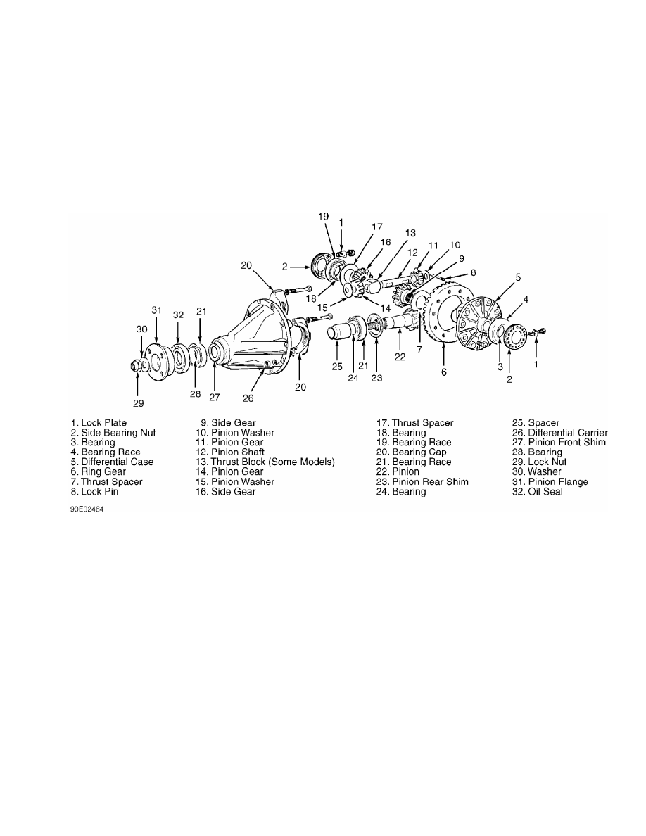
Fig. 3: Exploded View of Conventional Rear Differential
Courtesy of Chrysler Motors.
2) Using bearing puller, remove differential case side
bearings. Place alignment marks on ring gear and differential case for
reassembly. Loosen ring gear bolts in diagonal sequence. Remove ring
gear.
3) On conventional axles, remove drive pinion shaft lock pin
from differential case. Remove differential pinion shaft and thrust
block (if equipped). Remove pinion gears and washers. Remove side
gears and thrust spacers. Mark components for reassembly reference.
4) On limited slip units, mark differential case and
differential case cover for reassembly reference. Remove differential
case retaining screws. Separate differential case and cover. Remove
components from case. See Fig. 4. Mark components for location.
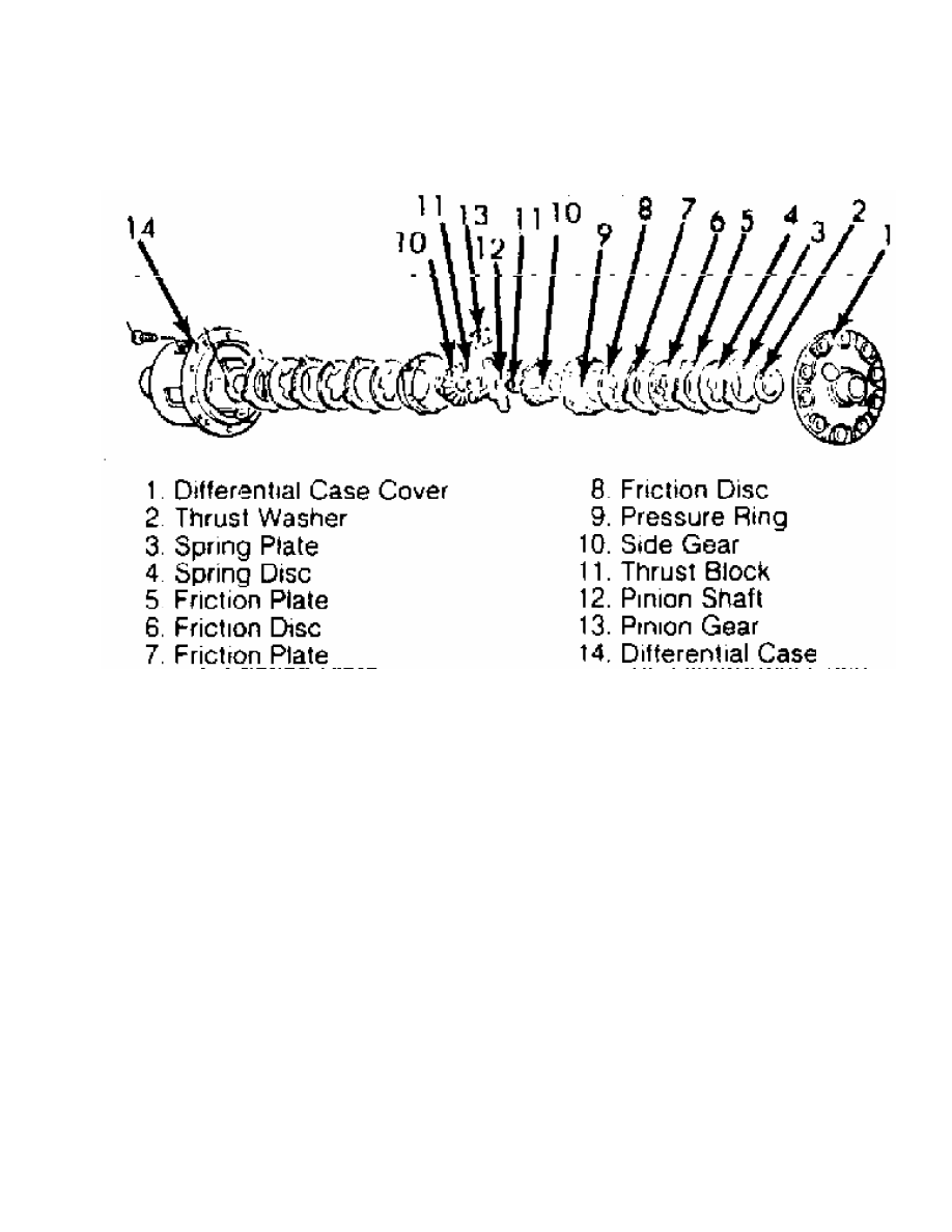
Fig. 4: Exploded View of Typical Limited Slip Differential
Courtesy of Chrysler Motors.
Drive Pinion
1) Remove pinion flange retaining nut. Scribe alignment marks
on drive pinion and pinion flange for reassembly. Using soft-faced
hammer, drive out pinion. Remove front adjusting shim and spacer from
pinion.
2) Using bearing puller, remove rear bearing from pinion.
Remove rear adjusting shim from pinion. Remove oil seal and bearing
races from differential carrier.
Inspection
1) Inspect all gears for cracked or flaking teeth. Inspect
pinion shaft for wear. Inspect pinion flange and drive pinion for
damaged splines.
2) Inspect bearings and races for roughness or flaking.
Replace worn components. On limited slip axles, inspect clutch
components and contact areas for wear or overheating. Inspect friction
plates, friction discs, spring plates and pressure rings for signs of
seizure, excessive heat, severe friction or nicks.
NOTE: Outer areas of friction surfaces will wear heavier due to
clutch plate and preload spring.
3) Using dial indicator, check friction plate and friction
disc for warpage. Replace components if beyond specification. See
FRICTION PLATE & DISC SPECIFICATIONS table.
4) Measure friction plates and disc thickness at projection
areas not within wear area. Measure plate and disc thickness in
friction surface. Difference between thickness of projections and
friction surface indicates amount of wear. Replace components if not
within specification. See FRICTION PLATE & DISC SPECIFICATIONS table.
FRICTION PLATE & DISC SPECIFICATIONS
Application In. (mm)
Warpage Limit . . . . . . . .003 (.08)
Wear Limit . . . . . . . .004 (.10)
DIFFERENTIAL OVERHAUL
CASE ASSEMBLY (CONVENTIONAL)
1) Install thrust spacers, side gears, pinion washers and
pinion gears in differential case. DO NOT install thrust block (if
equipped) at this time.
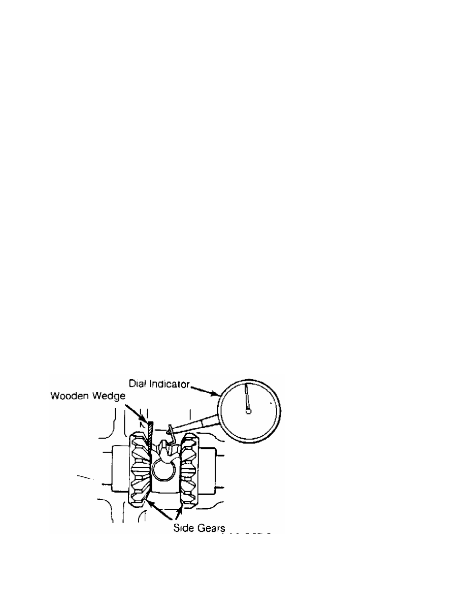
2) Install pinion shaft without lock pin. Check pinion and
side gear backlash. Install wooden wedge to lock side gears. Using
dial indicator, measure gear backlash. See Fig. 5.
3) Backlash must be within specification. See PINION & SIDE
GEAR BACKLASH SPECIFICATIONS table. Adjust backlash by using different
side gear spacers. Ensure both sides are equally shimmed.
PINION & SIDE GEAR BACKLASH SPECIFICATIONS
Application In. (mm)
4-Cylinder Engine
Standard . . . . .. .0004-.0030 (.010-.076)
Wear Limit . . . . . . . . .008 (.20)
V6 Engine
Standard . . . . . . . 0-.0030 (0-.076)
Wear Limit . . . . . . . . .008 (.20)
Fig. 5: Checking Pinion & Side Gear Backlash
Courtesy of Chrysler Motors.
4) Install thrust block (if equipped) once correct backlash
is obtained. Install pinion shaft lock pin from back side of ring
Нет комментариевНе стесняйтесь поделиться с нами вашим ценным мнением.
Текст