Mitsubishi Montero (1991+). Manual — part 71
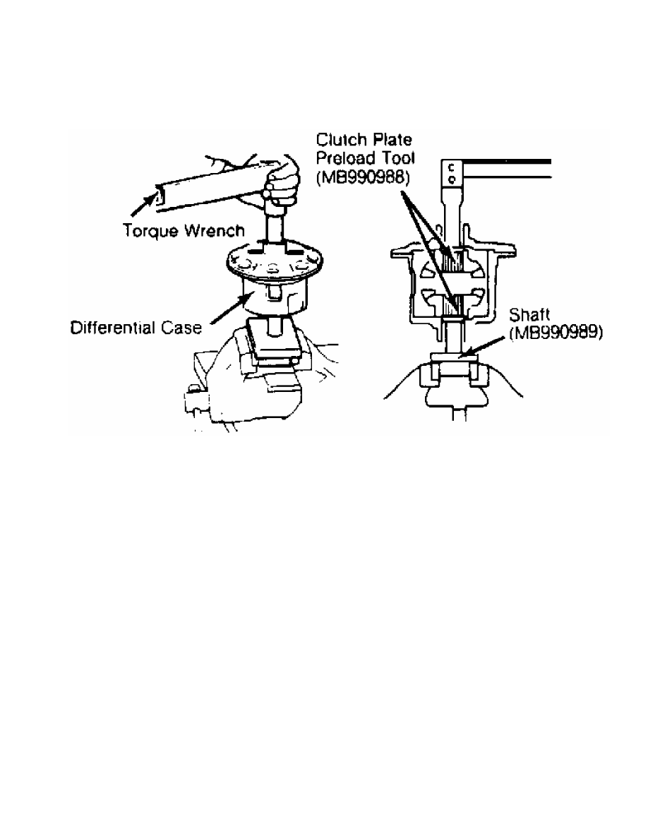
Fig. 10: Checking Differential Starting Torque
Courtesy of Chrysler Motors.
14) Starting torque must be within specification. See
STARTING TORQUE SPECIFICATIONS table. Ensure adhesive is removed from
ring gear mounting bolts and gear mounting surface. Clean internal
threads with tap.
15) Ensure alignment marks on differential case and ring gear
are aligned. Apply Loctite 271 to bolts and install ring gear on
differential case. Tighten bolts in diagonal sequence to
specification. See TORQUE SPECIFICATIONS table.
STARTING TORQUE SPECIFICATIONS
Application Ft. Lbs. (N.m)
Used Clutch Plates . . . . .. 25-72 (34-98)
New Clutch Plates . . . . ... 47-72 (64-98)
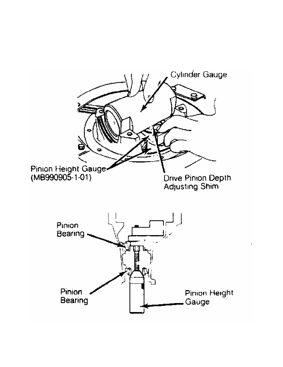
DRIVE PINION HEIGHT
1) Install pinion bearing races in carrier. Ensure races are
fully seated. Install pinion height gauge and pinion bearings. Use
Pinion Height Gauge (MB990901) for all others. See Fig. 10. DO NOT
install oil seal.
2) Using torque wrench, measure pinion rotating torque.
Gradually tighten pinion height gauge to increase rotating torque to
3.5-4.3 INCH lbs. (.40-.48 N.m).
3) Install cylinder gauge in side bearing seats. Ensure flat
areas are aligned and gauge contacts side bearing seat firmly. See
Fig. 11. Select adjusting shim with same thickness as gap between
cylinder gauge and pinion height gauge.
4) Use minimum amount of adjusting shims. Install selected
adjusting shims between drive pinion gear and rear pinion bearing.
Using bearing installer, install rear pinion bearing.
Fig. 11: Setting Pinion Height
Courtesy of Chrysler Motors.
DRIVE PINION PRELOAD
1) Install drive pinion in differential carrier. Install
spacer, pinion front shim(s) and front pinion bearing. DO NOT install
oil seal. Install pinion flange, washer and retaining nut. Tighten nut
to specification. See TORQUE SPECIFICATIONS table.
2) Check pinion rotating torque. Rotating torque must be
within specification. Correct specification is 3.5-4.3 INCH lbs. (.40-
.48 N.m) without oil seal. Adjust rotating torque by replacing drive
pinion front shims or spacer.
3) Once correct rotating torque is obtained, install oil
seal. Coat seal lip with grease. Install pinion flange so alignment
marks are correct. Apply light coat of grease to contact area of
pinion flange washer.
4) Install new retaining nut. Recheck pinion rotating torque.
Rotating torque must be within specification.
SIDE BEARING
1) Press side bearings onto differential case. Install outer
races. Install differential case into differential carrier. Align
bearing cap index marks, and snug carrier cap bolts. Ensure outer
races and bearing caps are installed in original location. Tighten
bearing cap bolts finger tight.
2) Install side bearing nuts. Tighten bearing cap bolts. See
TORQUE SPECIFICATIONS table. Rotate bearing nuts in and out until
rotation is smooth. Temporarily tighten side bearing nuts to preload
side bearings. See TORQUE SPECIFICATIONS table. Adjust ring gear
backlash.
RING GEAR BACKLASH
1) Lock drive pinion in place. Using dial indicator, check
ring gear backlash at heel of ring gear tooth. Measure at 4 locations
of ring gear. Gear backlash must be within specification. See RING
GEAR BACKLASH SPECIFICATIONS table.
RING GEAR BACKLASH SPECIFICATIONS
Application In. (mm)
2.4L . . . . . ... .0043-.0063 (.109-.160)
3.0L . . . . . ... .0051-.0071 (.130-.180)
2) If backlash is less than specification, loosen side
bearing nut at back of ring gear and tighten side bearing nut on tooth
side of ring gear by same amount. If backlash is beyond specification,
loosen side bearing nut at tooth side of ring gear and tighten side
bearing nut at back of ring gear by same amount.
3) After adjusting backlash, tighten both side bearing nuts
half the distance between center of 2 neighboring holes on side
bearing nut. Recheck backlash. Ensure bearing cap bolts are tightened
to specification. See TORQUE SPECIFICATIONS table.
4) Lock plates are of 2 designs for hole location of side
bearing nuts. Install proper type lock plate. Tighten lock plate bolt
to specification. See TORQUE SPECIFICATIONS table. Check gear tooth
contact using paint impression method. See GEAR TOOTH CONTACT PATTERNS
in this article.
RING GEAR RUNOUT
Using dial indicator, measure runout at back side of ring
gear. Runout must be within .002" (.05 mm). If runout is excessive,
change ring gear-to-differential case mounting position. Recheck
runout.
TORQUE SPECIFICATIONS
TORQUE SPECIFICATIONS
Application Ft. Lbs. (N.m)
Axle Bearing Lock Nut (Montero) . . . . .. 130-159 (176-216)
Bearing Cap Bolt . . . . . . . . . . 40-47 (54-64)
Bearing Case-To-Axle Housing Bolt . . . . . 36-43 (49-58)
Brake Tube Flare Nut . . . . . . . . . 10-12 (14-16)
Differential Carrier-To-Axle Housing Nut
2.4L (2WD) . . . . . . . . . . . 18-22 (24-30)
3.0L (4WD) . . . . . . . . . . . 29-40 (39-54)
Drain Plug . . . . . . . . . . ... 43-50 (58-68)
Filler Plug . . . . . . . . . . .. 29-43 (39-58)
Lock Plate Bolt . . . . . . . . . .. 11-16 (15-22)
Pinion Flange Nut . . . . . . . . 137-181 (186-245)
Drive Shaft-To-Flange Bolt . . . . . . ... 36-43 (49-58)
Ring Gear Bolt . . . . . . . . . ... 58-65 (79-88)
Side Bearing Lock Plate Bolts . . . . . . 11-16 (15-22)
Wheel Lug Nut
Montero . . . . . . . . . . ... 72-87 (98-118)
Pickup . . . . . . . . . . .. 87-101 (118-137)
Нет комментариевНе стесняйтесь поделиться с нами вашим ценным мнением.
Текст