Mitsubishi Montero (1991+). Manual — part 295
specification, use the following trouble shooting guide.
* Hydraulic Pressure High In All Ranges
Check throttle cable adjustment. If adjustment is okay, check
for throttle valve or regulator valve failure.
* Hydraulic Pressure Low In All Ranges
Check throttle cable adjustment. If adjustment is okay, check
for throttle valve, regulator valve, transmission oil pump or
overdrive clutch failure.
* Hydraulic Pressure Low In Drive Position
Check for fluid leaks in Drive hydraulic circuit. Check for
forward clutch or overdrive clutch failure.
* Hydraulic Pressure Low In Reverse Position
Check for fluid leaks in Reverse hydraulic circuit. Check for
transmission No. 3 brake failure, forward clutch failure or
overdrive clutch failure.
LINE PRESSURE (PICKUP)
1) Incorrect throttle pressure setting will cause incorrect
line pressure readings even though line pressure adjustment is
correct. Always inspect and correct throttle pressure adjustment
before adjusting line pressure.
2) Approximate adjustment, measured from valve body to inner
edge of adjusting nut, is 15/16". However, due to manufacturing
tolerances, adjustment can be varied to obtain correct line pressure.
3) Adjusting screw may be turned with an Allen wrench. One
complete turn of adjusting screw changes closed throttle line pressure
approximately 1 2/3 psi. Turn adjusting screw counterclockwise to
increase pressure or clockwise to decrease pressure.
THROTTLE PRESSURE (PICKUP)
1) Throttle pressures cannot be accurately tested. If a
malfunction exists, adjustment should be measured.
2) Insert Gauge Pin (C-3763) between throttle lever cam and
kickdown valve. Push in on tool to compress kickdown valve against its
spring.
3) As force is being exerted to compress spring, turn
throttle lever screw with Allen wrench until head of screw touches
throttle lever tang with gauge pin, and throttle valve bottoms. Ensure
adjustment is made with spring fully compressed and valve bottomed in
valve body.
KICKDOWN BAND
PICKUP
1) Locate kickdown band adjusting screw on left side of
transmission case. Loosen lock nut, and back off nut 5 turns. Ensure
adjusting screw turns freely in transmission case.
2) Using torque wrench, tighten adjusting screw to 72 INCH
lbs. (8 N.m). Back off adjusting screw 2 7/8 turns. Hold adjuster
screw in this position, and tighten lock nut to 30 ft. lbs. (41 N.m).
LOW-REVERSE BAND
PICKUP
1) Raise vehicle, drain transmission, and remove oil pan.
Loosen adjusting screw lock nut, and back off nut 5 turns. Ensure
adjusting screw turns freely in lever.
2) Using torque wrench, tighten band adjusting screw to 30
INCH lbs. (3.5 N.m). Back off adjusting screw 6 turns. Hold adjusting
screw in this position, and tighten lock nut to 25 ft. lbs. (34 N.m).
3) Reinstall oil pan using new gasket. Tighten pan bolts to
150 INCH lbs. (17 N.m). Refill with specified transmission fluid.
KICKDOWN SERVO
ECLIPSE, GALANT, MIRAGE, PRECIS & 3000GT
1) Remove all dirt and grease around kickdown servo switch.
Remove snap ring and kickdown servo switch.
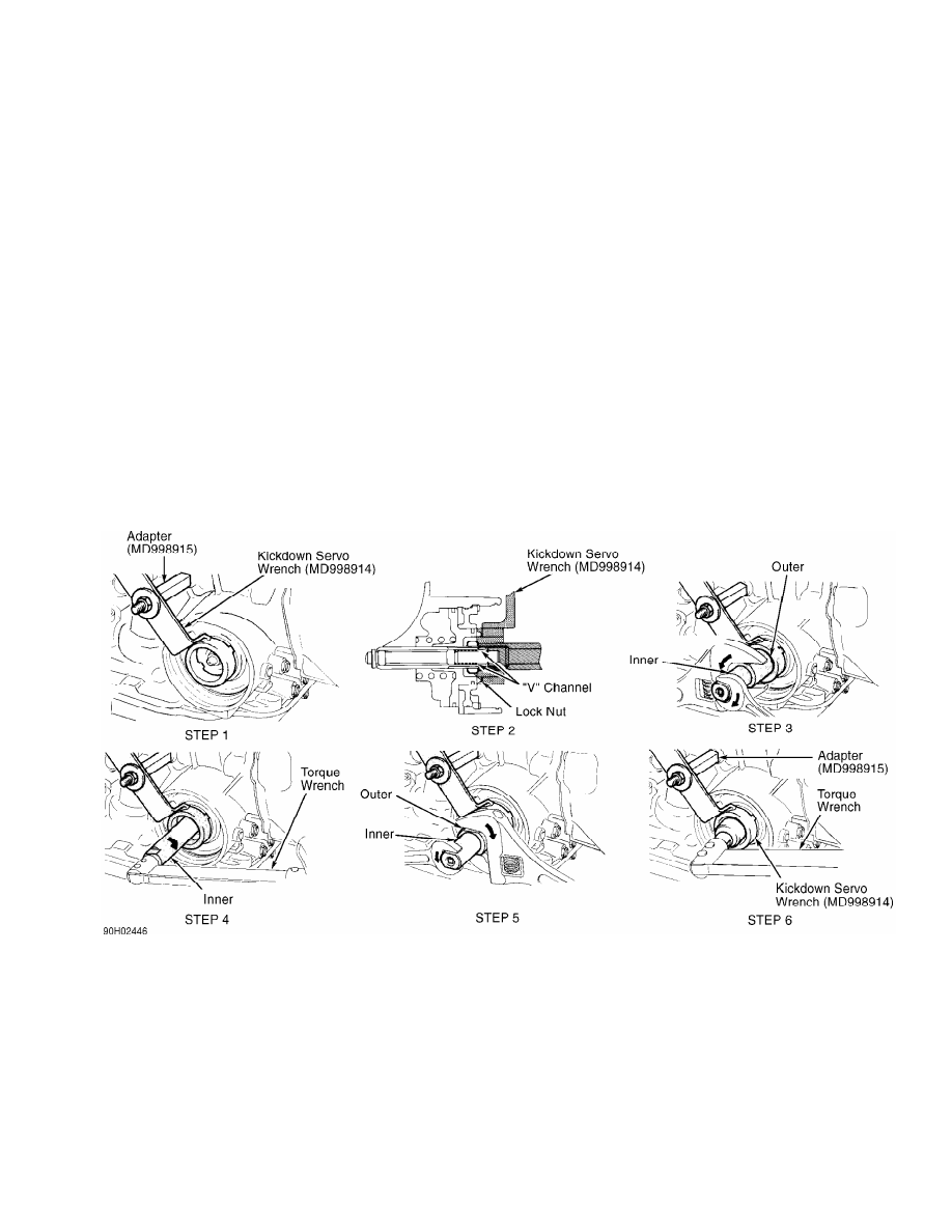
2) To prevent servo piston from turning, install Adapter
(MD998915) and Kickdown Servo Wrench (MD998914) so tab of wrench
engages with notch of piston. See Fig. 2.
CAUTION: DO NOT push servo piston inward while installing adapter
and servo wrench. Install adapter in brake pressure port by
hand ONLY. DO NOT use wrench to tighten adapter.
Fig. 2: Adjusting Kickdown Servo (Except Montero & Pickup)
Courtesy of Mitsubishi Motor Sales of America.
3) Loosen lock nut to "V" channel of adjuster rod. See
Fig. 2. Tighten inner section of Kickdown Service Adjustment Assembly
(MD998916) until it contacts lock nut.
4) Install outer section of kickdown service adjustment
assembly on lock nut. Rotate outer section to left and inner section
to right to contact lock nut with inner section.
5) Using an INCH lb. torque wrench on inner section, tighten
inner section to 86 INCH lbs. (9.8 N.m), and then loosen inner
section. Tighten inner section to 43 INCH lbs. (4.9 N.m).
CAUTION: Before tightening lock nut with torque wrench, tighten it
by hand until it contacts piston. If torque wrench is used
initially, lock nut and adjustment rod may rotate together.
6) Back off outer section 2-2 3/4 turns. Rotate outer section
to right and inner section to left until inner section is free of lock
nut. Tighten lock nut by hand until it contacts piston. Using torque
wrench, tighten lock nut to 18-23 ft. lbs. (25-32 N.m).
7) Remove adapter and kickdown servo wrench. Install new "O"
ring in groove around switch. Install switch and snap ring.
TRANSMISSION THROTTLE CONTROL
MIRAGE
1) On all other models, ensure throttle lever is in curb idle
position. Engine must be at normal operating temperature.
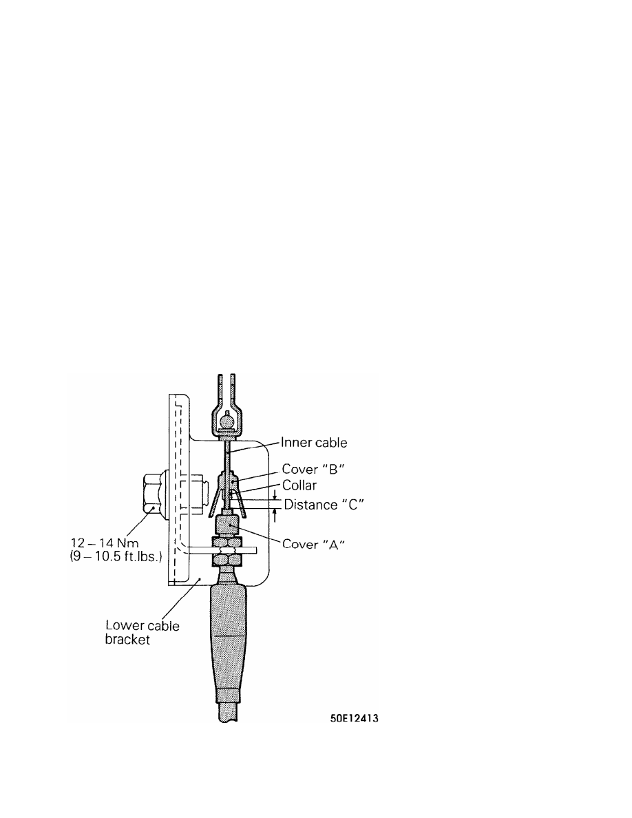
2) On all models, raise cover "B" of throttle cable upward to
expose nipple. See Fig. 3. Loosen lower cable bracket mounting bolt.
Move lower cable bracket until distance between nipple and top of
cover "A" on throttle cable is .02-.06" (.5-1.5 mm).
3) Tighten lower cable bracket mounting bolt to 108-126 INCH
lbs. (12-14 N.m). With throttle lever in wide open throttle position,
pull cable upward to ensure some cable free play exists.
Fig. 3: Adjusting Throttle Cable (Mirage)
Courtesy of Mitsubishi Motor Sales of America.
CAUTION: On Pickup, always adjust throttle control cable
whenever idle is adjusted.
PICKUP
1) Ensure engine idle is adjusted correctly. Ensure throttle
lever and throttle cable bracket are not bent. Pull lightly on inner
throttle cable.
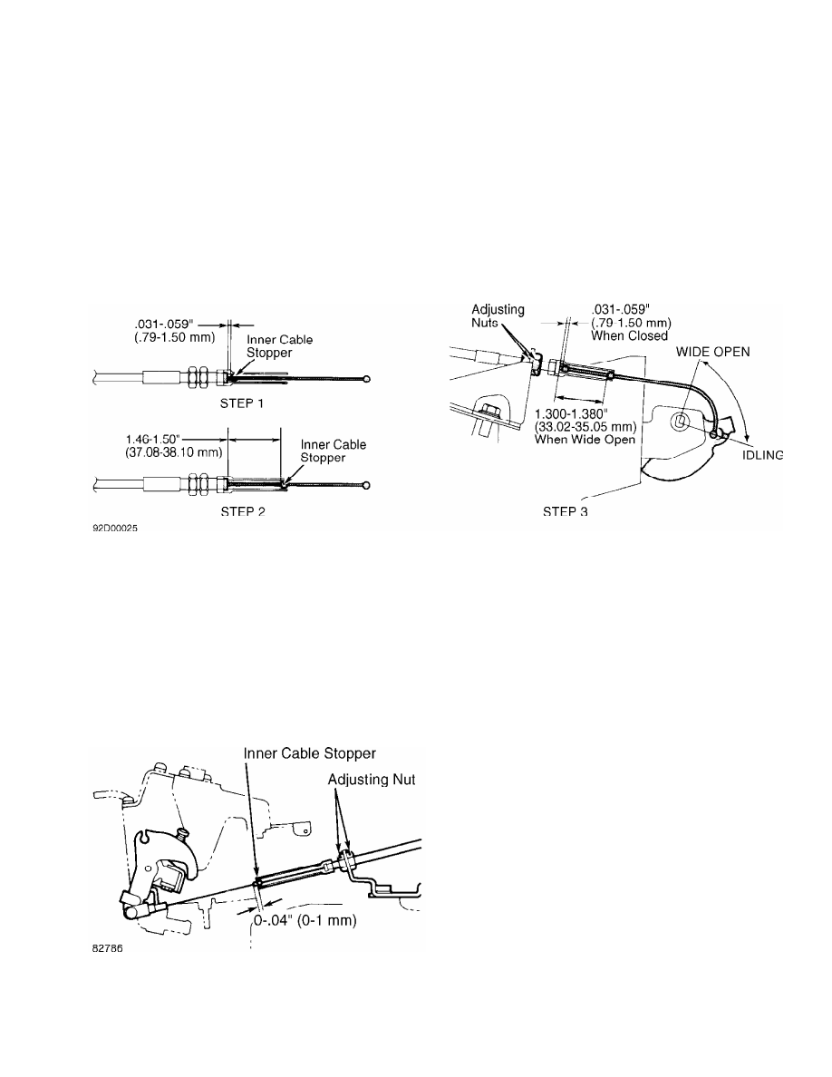
2) While in closed throttle position, measure gap between
inner cable stopper and outer cable housing. Adjust cable as necessary
to obtain a gap of .031-.059" (.79-1.50 mm). See Fig. 4 (STEP 1).
Fig. 4: Adjusting Throttle Cable (Pickup)
Courtesy of Mitsubishi Motor Sales of America.
3) While holding throttle in wide open position, pull on
inner throttle cable. Adjust bell crank as necessary to obtain a gap
of 1.46-1.50" (37.08-38.10 mm) between inner cable stopper and outer
cable. See Fig. 4 (STEP 2).
4) With throttle fully closed, recheck gap between inner
cable stopper and outer cable housing. Gap should be .031-.059" (.79-
1.50 mm). See Fig. 4 (STEP 3). While holding throttle in wide open
position, pull on inner throttle cable. Check for a gap of 1.30-1.38"
(33.02-35.05 mm).
Montero Ensure throttle lever and throttle cable bracket
are not bent. Ensure distance between inner cable stopper end and dust
cover is 0-.04" (0-1.0 mm). See Fig. 5.
Fig. 5: Adjusting Throttle Cable (Montero)
Courtesy of Mitsubishi Motor Sales of America.
SHIFT LINKAGE
Нет комментариевНе стесняйтесь поделиться с нами вашим ценным мнением.
Текст