Mitsubishi Eclipse / Eclipse Spyder (2000-2002). Service and repair manual — part 267
MULTIPORT FUEL INJECTION (MFI) DIAGNOSIS
TSB Revision
MULTIPORT FUEL INJECTION (MFI) <3.0L ENGINE>
13B-267
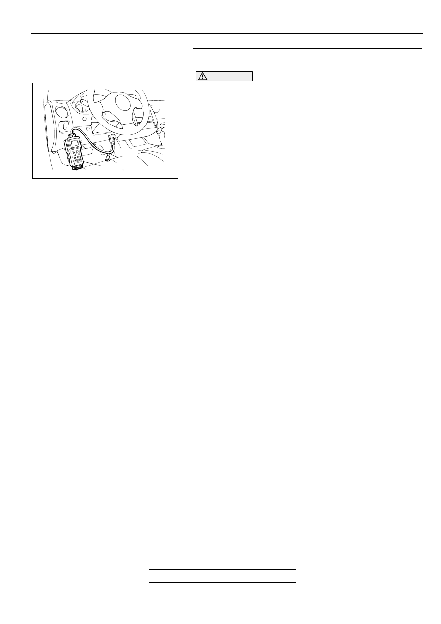
STEP 2. Using scan tool MB991502, check data list item 95:
Manifold Differential Pressure Sensor.
CAUTION
To prevent damage to scan tool MB991502, always turn the
ignition switch to the "LOCK" (OFF) position before
connecting or disconnecting scan tool MB991502.
(1) Connect scan tool MB991502 to the data link connector.
(2) Start the engine and run at idle.
(3) Set scan tool MB991502 to the data reading mode for item
95, Manifold Differential Pressure Sensor.
(4) Warm up the engine to normal operating temperature: 80
°
C to 96
°
C(176
°
F to 205
°
F).
•
Should be between 62
−
76 kPa at engine idling.
(5) Turn the ignition switch to the "LOCK" (OFF) position.
Q: Is the sensor operating properly?
YES : Clean the EGR valve and EGR passage. Then go to
Step 3.
NO : Refer to, DTC P1400
−
Manifold Differential Pressure
Sensor Circuit Malfunction (
STEP 3. Test the OBD-II drive cycle.
(1) Carry out a test drive with the drive cycle pattern. Refer to,
Procedure 5
−
Exhaust Gas Recirculation (EGR) System
Monitor (
).
(2) Check the diagnostic trouble code (DTC).
Q: Is the DTC P0401 is output?
YES : Retry the troubleshooting.
NO : The inspection is complete.
AKX01177
16 PIN
MB991502
AB
MULTIPORT FUEL INJECTION (MFI) DIAGNOSIS
TSB Revision
MULTIPORT FUEL INJECTION (MFI) <3.0L ENGINE>
13B-268
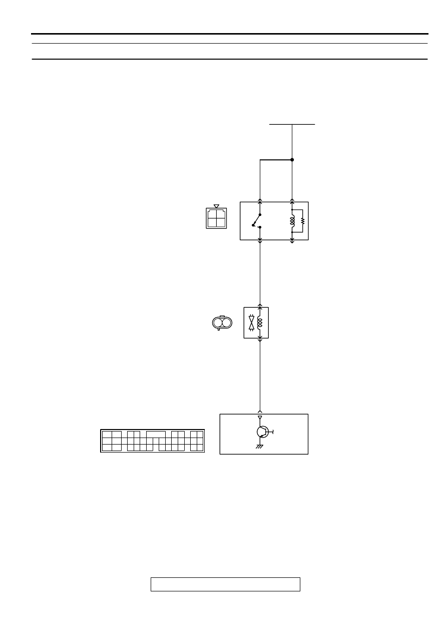
DTC P0403: Exhaust Gas Recirculation Solenoid Malfunction
AK000705
3 4
1 2
RED-
WHITE
RED-
WHITE
RED-
WHITE
BLUE-RED
RED
BATTERY
MFI
RELAY
A-21X
EGR SOLENOID
1
1
2
2
3
4
6
ENGINE CONTROL
MODULE(ECM)<M/T>
OR
POWERTRAIN CONTROL
MODULE(PCM)<A/T>
B-31
C-51<M/T>,C-52<A/T>
(MU803784)
2
3 4
5 6
7 8
9
11 12 13 14 15 16 17 18 19 20
30
2122 23
24 25
26 27 28 29
31 32 33
34 35
1
10
2
1
MULTIPORT FUEL INJECTION (MFI) DIAGNOSIS
TSB Revision
MULTIPORT FUEL INJECTION (MFI) <3.0L ENGINE>
13B-269
TECHNICAL DESCRIPTION
•
The EGR solenoid power is supplied from the
MFI relay (terminal 1).
•
The ECM <M/T> or PCM <A/T> controls the EGR
solenoid ground by turning the power transistor in
the ECM <M/T> or PCM <A/T> "ON" and "OFF."
BACKGROUND
•
The ECM <M/T> or PCM <A/T> checks current
flows in the EGR solenoid drive circuit when the
EGR solenoid is "ON" and "OFF."
DTC SET CONDITIONS
Check Conditions
•
Battery positive voltage is higher than 10 volts.
Judgment Criteria
•
The EGR solenoid coil surge voltage (battery
positive voltage + 2 volts) is not detected when
the EGR solenoid is turned from "ON" to "OFF."
•
Only one monitor during one drive cycle
TROUBLESHOOTING HINTS (The most likely
causes for this code to be set are:)
•
EGR solenoid failed.
•
Open or shorted EGR solenoid circuit, or loose
connector.
•
ECM failed. <M/T>
•
PCM failed. <A/T>
DIAGNOSIS
Required Special Tools
MB991502: Scan Tool (MUT-II)
ACX02514
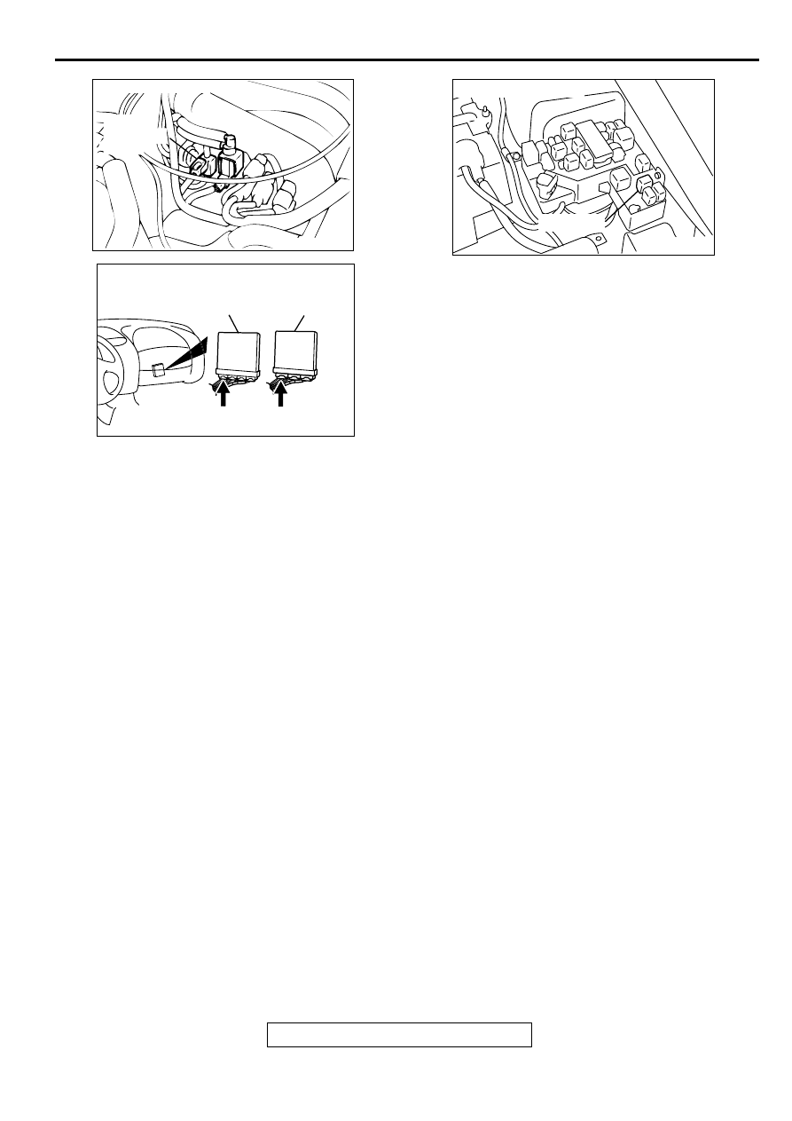
CONNECTOR:B-31
EGR
SOLENOID
VALVE
AJ
AK000225
CONNECTOR : C-51<M/T>, C-52<A/T>
C-52
C-51
PCM<A/T>
ECM<M/T>
AJ
AK000226
AK000226AB
CONNECTOR : A-21X
MFI RELAY
MULTIPORT FUEL INJECTION (MFI) DIAGNOSIS
TSB Revision
MULTIPORT FUEL INJECTION (MFI) <3.0L ENGINE>
13B-270
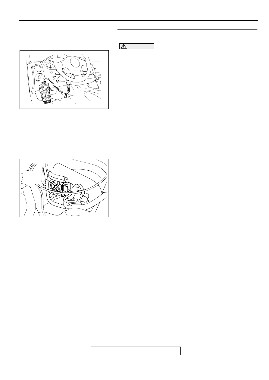
STEP 1. Using scan tool MB991502, check actuator test
item 10: EGR solenoid.
CAUTION
To prevent damage to scan tool MB991502, always turn the
ignition switch to the "LOCK" (OFF) position before
connecting or disconnecting scan tool MB991502.
(1) Connect scan tool MB991502 to the data link connector.
(2) Turn the ignition switch to the "ON" position.
(3) Set scan tool MB991502 to the actuator test mode for item
10, EGR solenoid.
•
An operation sound should be heard and vibration
should be felt when the EGR solenoid is operated.
(4) Turn the ignition switch to the "LOCK" (OFF) position.
Q: Is the solenoid operating properly?
YES : It can be assumed that this malfunction is intermittent.
Refer to GROUP 00, How to Use Troubleshooting/
Inspection Service Points (
NO : Go to Step 2.
STEP 2. Check connector B-31 at the EGR solenoid for
damage.
Q: Is the connector in good condition?
YES : Go to Step 3.
NO : Repair or replace it. Refer to GROUP 00E, Harness
Connector Inspection (
). Then go to Step 12.
AKX01177
16 PIN
MB991502
AB
ACX02514
CONNECTOR:B-31
EGR
SOLENOID
VALVE
AJ
Нет комментариевНе стесняйтесь поделиться с нами вашим ценным мнением.
Текст