Mitsubishi Eclipse / Eclipse Spyder (2000-2002). Service and repair manual — part 268
MULTIPORT FUEL INJECTION (MFI) DIAGNOSIS
TSB Revision
MULTIPORT FUEL INJECTION (MFI) <3.0L ENGINE>
13B-271
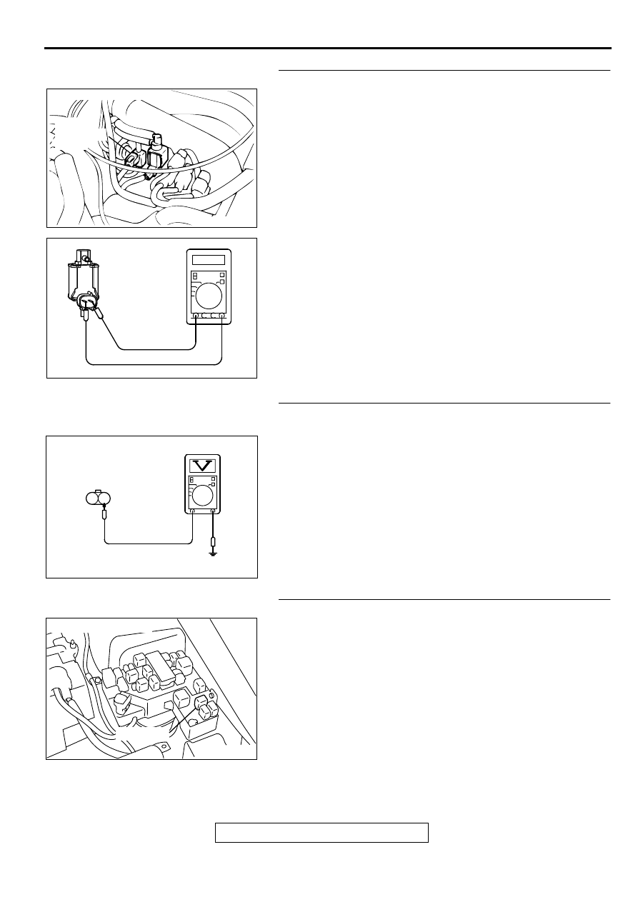
STEP 3 Check the EGR solenoid.
(1) Disconnect the EGR solenoid connector B-31.
(2) Measure the resistance between EGR solenoid side
connector terminal 1 and 2.
Standard value: 29
−
35
Ω
[at 20
°
C (68
°
F)]
Q: Is the resistance at the standard value?
YES : Go to Step 4.
NO : Replace the EGR solenoid. Then go to Step 12.
STEP 4. Check the power supply voltage at EGR solenoid
harness side connector B-31.
(1) Disconnect the connector B-31 and measure at the harness
side.
(2) Turn the ignition switch to the "ON" position.
(3) Measure the voltage between terminal 1 and ground.
•
Voltage should be battery positive voltage
(4) Turn the ignition switch to the "LOCK" (OFF) position.
Q: Is the voltage normal?
YES : Go to Step 6.
NO : Go to Step 5.
STEP 5. Check connector A-21X at MFI relay for damage.
Q: Is the connector in good condition?
YES : Repair harness wire between MFI relay connector A-
21X terminal 1 and EGR solenoid connector B-31
terminal 1 because of open circuit or short circuit to
ground. Then go to Step 12.
NO : Repair or replace it. Refer to GROUP 00E, Harness
Connector Inspection (
). Then go to Step 12.
ACX02514
CONNECTOR:B-31
EGR
SOLENOID
VALVE
AJ
AKX00352
AK000254AF
B-31 HARNESS
SIDE CONNECTOR
2 1
AK000226
AK000226AB
CONNECTOR : A-21X
MFI RELAY
MULTIPORT FUEL INJECTION (MFI) DIAGNOSIS
TSB Revision
MULTIPORT FUEL INJECTION (MFI) <3.0L ENGINE>
13B-272
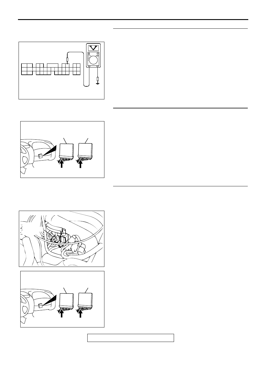
STEP 6. Check the power supply voltage at ECM connector
C-51 <M/T> or PCM connector C-52 <A/T> by backprobing
(1) Do not disconnect the connector C-51 <M/T> or C-52 <A/
T>.
(2) Turn the ignition switch to the "ON" position.
(3) Measure the voltage between terminal 6 and ground by
backprobing.
•
Voltage should be battery positive voltage.
(4) Turn the ignition switch to the "LOCK" (OFF) position.
Q: Is the voltage normal?
YES : Go to Step 9.
NO : Go to Step 7.
STEP 7. Check connector C-51 at ECM <M/T> or connector
C-52 at PCM <A/T> for damage.
Q: Is the connector in good condition?
YES : Go to Step 8.
NO : Repair or replace it. Refer to GROUP 00E, Harness
Connector Inspection (
). Then go to Step 12.
STEP 8. Check for open circuit and short circuit to ground
between EGR solenoid connector B-31 terminal 2 and ECM
connector C-51 terminal 6 <M/T> or PCM connector C-52
terminal 6 <A/T>.
Q: Is the harness wire in good condition?
YES : Replace the ECM or PCM. Then go to Step 12.
NO : Repair it. Then go to Step 12.
AKX01546
1
2
3 4
5 6
7 8
10 11 12 13 14 15 16 17 18 19 20 21 22 23
24 25
26 27 28 29
30 31 32 33
34 35
C-51<M/T>, C-52<A/T>
CONNECTOR HARNESS
SIDE VIEW
AE
9
AK000225
CONNECTOR : C-51<M/T>, C-52<A/T>
C-52
C-51
PCM<A/T>
ECM<M/T>
AJ
ACX02514
CONNECTOR:B-31
EGR
SOLENOID
VALVE
AJ
AK000225
CONNECTOR : C-51<M/T>, C-52<A/T>
C-52
C-51
PCM<A/T>
ECM<M/T>
AJ
MULTIPORT FUEL INJECTION (MFI) DIAGNOSIS
TSB Revision
MULTIPORT FUEL INJECTION (MFI) <3.0L ENGINE>
13B-273
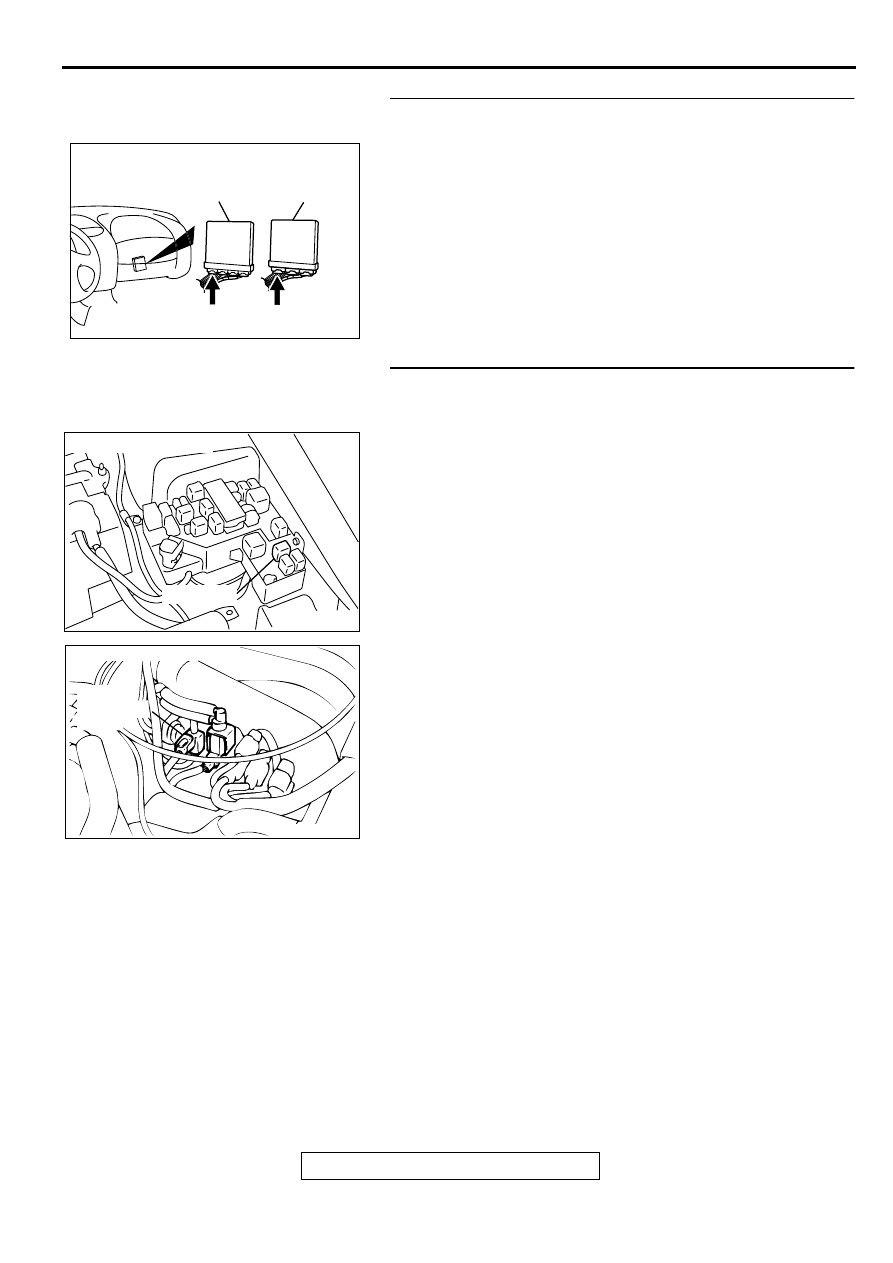
STEP 9. Check connector C-51 at ECM <M/T> or connector
C-52 at PCM <A/T> for damage.
Q: Is the connector in good condition?
YES : Go to Step 10.
NO : Repair or replace it. Refer to GROUP 00E, Harness
Connector Inspection (
). Then go to Step 12.
STEP 10. Check for harness damage between MFI relay
connector A-21X terminal 1 and EGR solenoid connector
B-31 terminal 1.
Q: Is the harness wire in good condition?
YES : Go to Step 11.
NO : Repair it. Then go to Step 12.
AK000225
CONNECTOR : C-51<M/T>, C-52<A/T>
C-52
C-51
PCM<A/T>
ECM<M/T>
AJ
AK000226
AK000226AB
CONNECTOR : A-21X
MFI RELAY
ACX02514
CONNECTOR:B-31
EGR
SOLENOID
VALVE
AJ
MULTIPORT FUEL INJECTION (MFI) DIAGNOSIS
TSB Revision
MULTIPORT FUEL INJECTION (MFI) <3.0L ENGINE>
13B-274
STEP 11. Check for harness damage between EGR
solenoid connector B-31 terminal 2 and ECM connector C-
51 terminal 6 <M/T> or PCM connector C-52 terminal 6 <A/
T>.
Q: Is the harness wire in good condition?
YES : Replace the ECM or PCM. Then go to Step 12.
NO : Repair it. Then go to Step 12.
STEP 12. Test the OBD-II drive cycle.
(1) Carry out a test drive with the drive cycle pattern. Refer to,
Procedure 6
−
Other Monitor (
).
(2) Check the diagnostic trouble code (DTC).
Q: Is the DTC P0403 is output?
YES : Retry the troubleshooting.
NO : The inspection is complete.
DTC P0421: Warm Up Catalyst Efficiency Below Threshold (bank 1)
TECHNICAL DESCRIPTION
•
The signal from the rear heated oxygen sensor
differs from the front heated oxygen sensor. That
is because the catalytic converter purifies
exhaust gas. When the catalytic converter has
deteriorated, the signal from the front heated
oxygen sensor becomes similar to the rear
heated oxygen sensor.
•
The ECM <M/T> or PCM <A/T> compares the
output of the front and rear heated oxygen sensor
signals.
DTC SET CONDITIONS
Check Conditions
•
Engine speed is lower than 3,000 r/min.
•
Volume air flow sensor output frequency is
between 69 and 169 Hz.
•
Intake air temperature is higher than -10
°
C (14
°
F).
•
Barometric pressure is higher than 76 kPa (11
psi).
•
The throttle valve is open.
•
Under the closed loop air / fuel ratio control.
•
Vehicle speed is 1.5 km/h (0.93 mph) or more.
•
Monitoring time: 84 seconds.
Judgment Criteria
•
The right bank heated oxygen sensor (rear)
signal and right bank heated oxygen sensor
(front) signal are similar.
TROUBLESHOOTING HINTS (The most likely
causes for this code to be set are:)
•
Right bank side catalytic converter deteriorated.
•
Right bank heated oxygen sensor failed.
•
ECM failed. <M/T>
•
PCM failed. <A/T>
DIAGNOSIS
Required Special Tools
MB991502: Scan Tool (MUT-II)
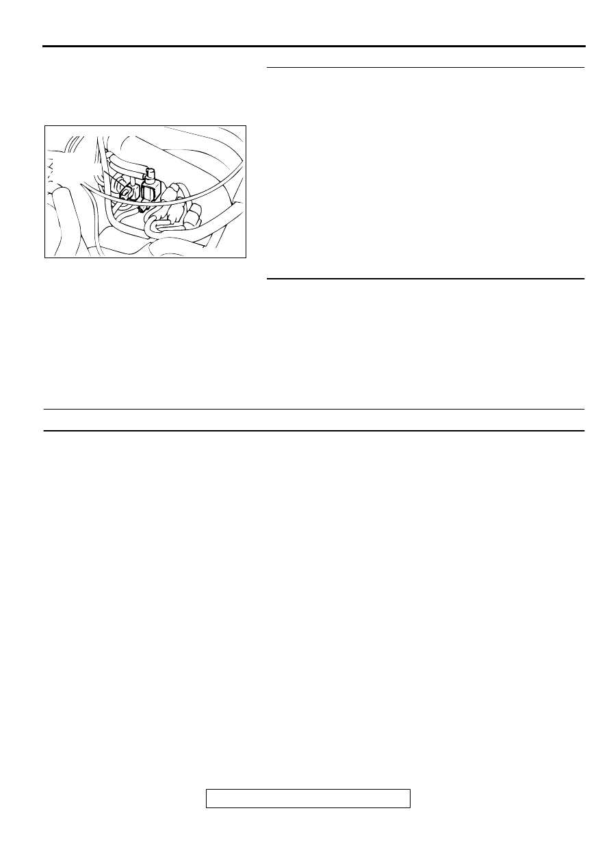
ACX02514
CONNECTOR:B-31
EGR
SOLENOID
VALVE
AJ
Нет комментариевНе стесняйтесь поделиться с нами вашим ценным мнением.
Текст