Mitsubishi Eclipse / Eclipse Spyder (2000-2002). Service and repair manual — part 265
MULTIPORT FUEL INJECTION (MFI) DIAGNOSIS
TSB Revision
MULTIPORT FUEL INJECTION (MFI) <3.0L ENGINE>
13B-259
CIRCUIT OPERATION
•
The camshaft position sensor power is supplied
from the MFI relay (terminal 1). Ground is
provided through terminal 7 to chassis ground.
•
A 5-volt voltage is applied on the camshaft
position sensor output terminal (terminal 5) from
the ECM (terminal 50) <M/T> or PCM (terminal
56) <A/T>. The camshaft position sensor
generates a pulse signal when the output
terminal is opened and grounded.
TECHNICAL DESCRIPTION
•
The camshaft position sensor functions to detect
the top dead center position of the number 1
cylinder and to convert that data to pulse signals
that are input to the ECM <M/T> or PCM <A/T>.
•
When the engine is running, the camshaft
position sensor outputs a pulse signal.
•
The ECM <M/T> or PCM <A/T> checks whether
pulse signal is input while the engine is cranking.
DTC SET CONDITIONS
Check Conditions
•
Engine speed is higher than 50 r/min.
Judgment Criteria
•
Camshaft position sensor output voltage has not
changed (no pulse signal is input) for 2 seconds.
Check Conditions
•
Engine speed is higher than 50 r/min.
Judgment Criteria
•
Normal signal pattern has not been input for
cylinder identification from the crankshaft position
sensor signal and camshaft position sensor
signal for 2 seconds.
TROUBLESHOOTING HINTS (The most likely
causes for this code to be set are:)
•
Camshaft position sensor failed.
•
Open or shorted camshaft position sensor circuit,
or loose connector.
•
ECM failed. <M/T>
•
PCM failed. <A/T>
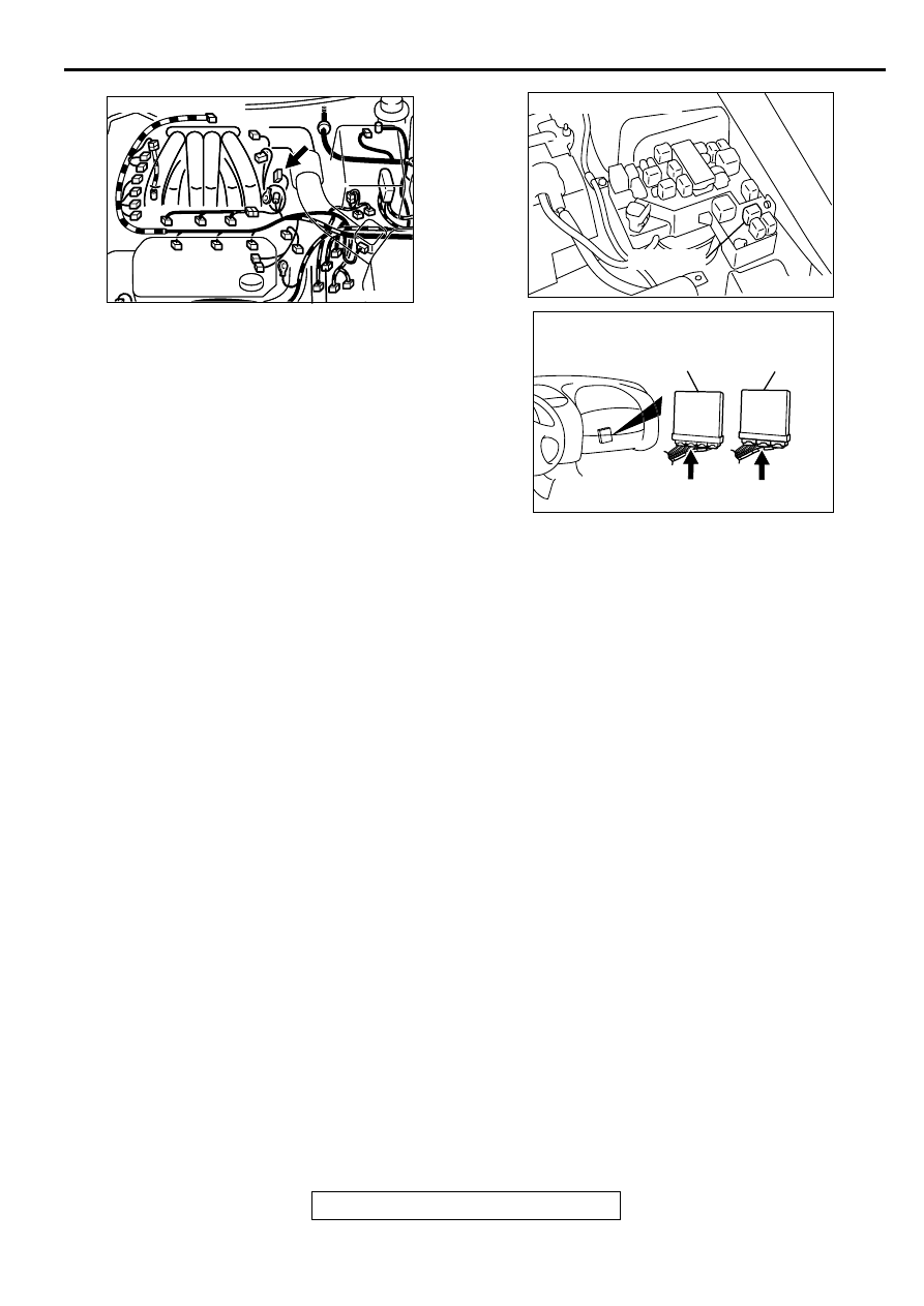
AK000217AB
AK000217
CONNECTOR : B-22
AK000226
AK000226AB
CONNECTOR : A-21X
MFI RELAY
AK000225
CONNECTOR : C-58<M/T>, C-55<A/T>
C-55
C-58
PCM<A/T>
ECM<M/T>
AI
MULTIPORT FUEL INJECTION (MFI) DIAGNOSIS
TSB Revision
MULTIPORT FUEL INJECTION (MFI) <3.0L ENGINE>
13B-260
DIAGNOSIS
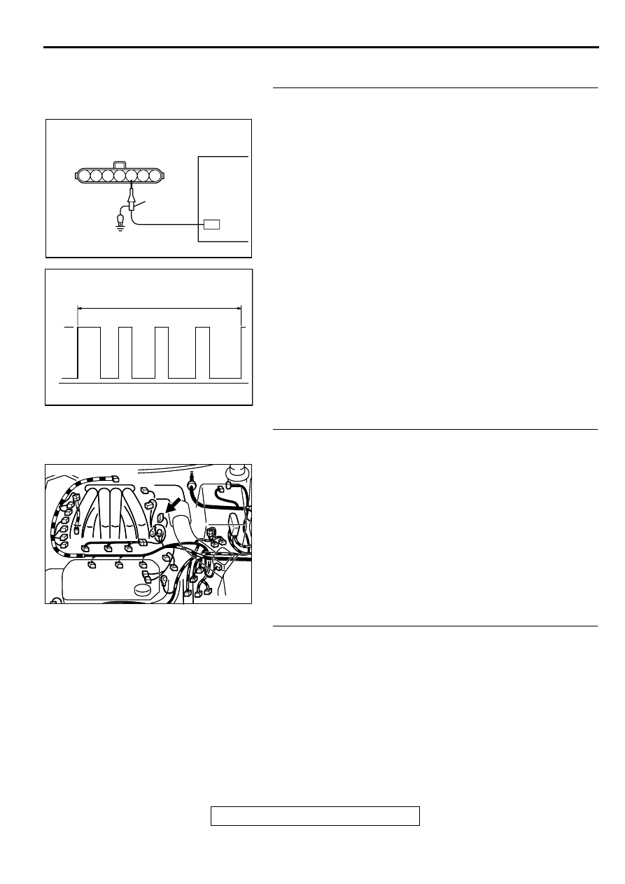
STEP 1. Using the oscilloscope, check the camshaft
position sensor.
(1) Disconnect the camshaft position sensor connector B-22,
and connect test harness special tool (MB991348) in
between. (All terminals should be connected.)
(2) Connect the oscilloscope probe to the camshaft position
sensor side connector terminal 5.
NOTE: When measuring with the ECM or PCM side
connector, connect an oscilloscope probe to terminal 50
<M/T> or terminal 56 <A/T>.
(3) Start the engine and run at idle.
(4) Check the waveform.
•
The waveform should show a pattern similar to the
illustration.
(5) Turn the ignition switch to the "LOCK" (OFF) position.
Q: Is the waveform normal?
YES : Go to Step 2.
NO : Go to Step 4.
STEP 2. Check connector B-22 at camshaft position
sensor for damage.
Q: Is the connector in good condition?
YES : Go to Step 3.
NO : Repair or replace it. Refer to GROUP 00E, Harness
Connector Inspection (
). Then go to Step 18.
STEP 3. Check the trouble symptoms.
(1) Carry out a test drive with the drive cycle pattern. Refer to,
Procedure 6
−
Other Monitor (
).
(2) Check the diagnostic trouble code (DTC).
Q: Is the DTC P0340 is output?
YES : Replace the ECM or PCM. Then go to Step 18.
NO : It can be assumed that this malfunction is intermittent.
Refer to GROUP 00, How to Use Troubleshooting/
Inspection Service Points (
AK000061
1 2 3 4 5 6 7
OSCILLOSCOPE
CAMSHAFT POSITION
SENSOR CONNECTOR
OSCILLO-
SCOPE
PROBE
AB
AKX01420AB
2 ENGINE REVOLUTIONS
NORMAL WAVEFORM
5V
AK000217AB
AK000217
CONNECTOR : B-22
MULTIPORT FUEL INJECTION (MFI) DIAGNOSIS
TSB Revision
MULTIPORT FUEL INJECTION (MFI) <3.0L ENGINE>
13B-261
STEP 4. Check connector B-22 at camshaft position
sensor for damage.
Q: Is the connector in good condition?
YES : Go to Step 5.
NO : Repair or replace it. Refer to GROUP 00E, Harness
Connector Inspection (
). Then go to Step 18.
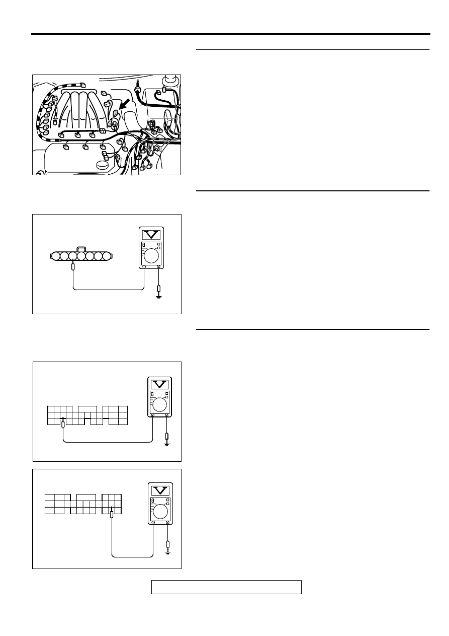
STEP 5. Check the sensor supply voltage at camshaft
position sensor connector B-22.
(1) Disconnect the connector B-22 and measure at the harness
side.
(2) Turn the ignition switch to the "ON" position.
(3) Measure the voltage between terminal 5 and ground.
•
Voltage should be between 4.8 and 5.2 volts
(4) Turn the ignition switch to the "LOCK" (OFF) position.
Q: Is the voltage normal?
YES : Go to Step 10.
NO : Go to Step 6.
STEP 6. Check the sensor supply voltage at ECM
connector C-58 <M/T> or PCM connector C-55 <A/T> by
backprobing
(1) Do not disconnect the ECM connector C-58 <M/T> or PCM
connector C-55 <A/T>.
(2) Disconnect the camshaft position sensor connector B-22.
(3) Turn the ignition switch to the "ON" position.
(4) Measure the voltage between terminal 50 <M/T> or 56 <A/
T> and ground by backprobing.
•
Voltage should be between 4.8 and 5.2 volts.
(5) Turn the ignition switch to the "LOCK" (OFF) position.
Q: Is the voltage normal?
YES : Go to Step 7.
NO : Go to Step 8.
AK000217AB
AK000217
CONNECTOR : B-22
AK000250AB
B-22 HARNESS
SIDE CONNECTOR
7 6 5 4 3 2 1
AK000251
41424344
48
50 51
49
52 5354555657 58 59
45 46 47
60 61
626364
65
67 68
66
AK000251AC
C-58 CONNECTOR
HARNESS SIDE VIEW
AKX01545
41
AE
C-55 CONNECTOR
HARNESS SIDE VIEW
42 43
44 45 46
47 48 49 50 51 52 53 54 55 56 57
58 59
60 61 62 63
64
66
MULTIPORT FUEL INJECTION (MFI) DIAGNOSIS
TSB Revision
MULTIPORT FUEL INJECTION (MFI) <3.0L ENGINE>
13B-262
STEP 7. Check connector C-58 at ECM <M/T> or connector
C-55 at PCM <A/T> for damage.
Q: Is the connector in good condition?
YES : Repair harness wire between camshaft position
sensor connector B-22 terminal 5 and ECM connector
C-58 terminal 50 <M/T> or PCM connector C-55
terminal 56 <A/T> because of open circuit. Then go to
Step 18.
NO : Repair or replace it. Refer to GROUP 00E, Harness
Connector Inspection (
). Then go to Step 18.
STEP 8. Check connector C-58 at ECM <M/T> or connector
C-55 at PCM <A/T> for damage.
Q: Is the connector in good condition?
YES : Go to Step 9.
NO : Repair or replace it. Refer to GROUP 00E, Harness
Connector Inspection (
). Then go to Step 18.
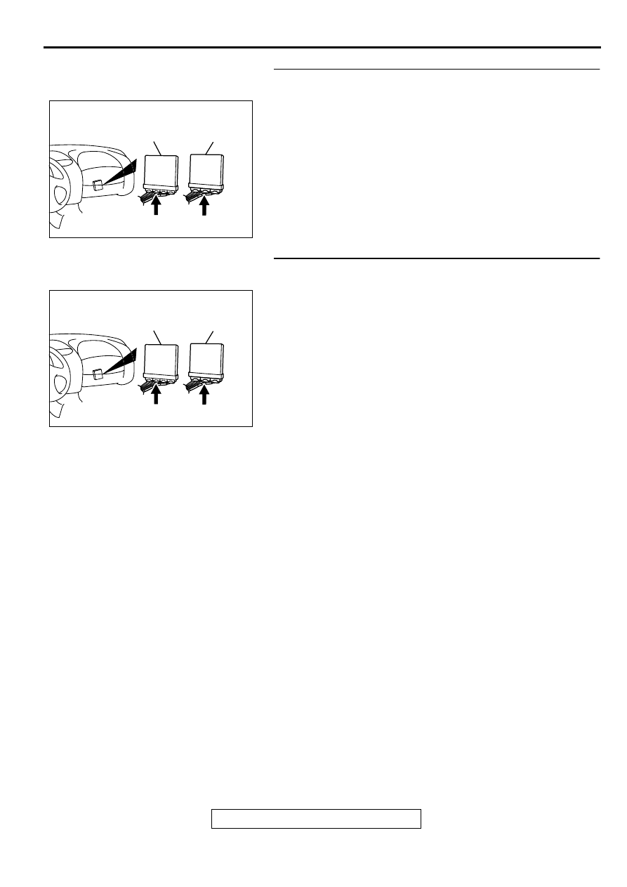
AK000225
CONNECTOR : C-58<M/T>, C-55<A/T>
C-55
C-58
PCM<A/T>
ECM<M/T>
AI
AK000225
CONNECTOR : C-58<M/T>, C-55<A/T>
C-55
C-58
PCM<A/T>
ECM<M/T>
AI
Нет комментариевНе стесняйтесь поделиться с нами вашим ценным мнением.
Текст