Mitsubishi Eclipse / Eclipse Spyder (2000-2002). Service and repair manual — part 266
MULTIPORT FUEL INJECTION (MFI) DIAGNOSIS
TSB Revision
MULTIPORT FUEL INJECTION (MFI) <3.0L ENGINE>
13B-263
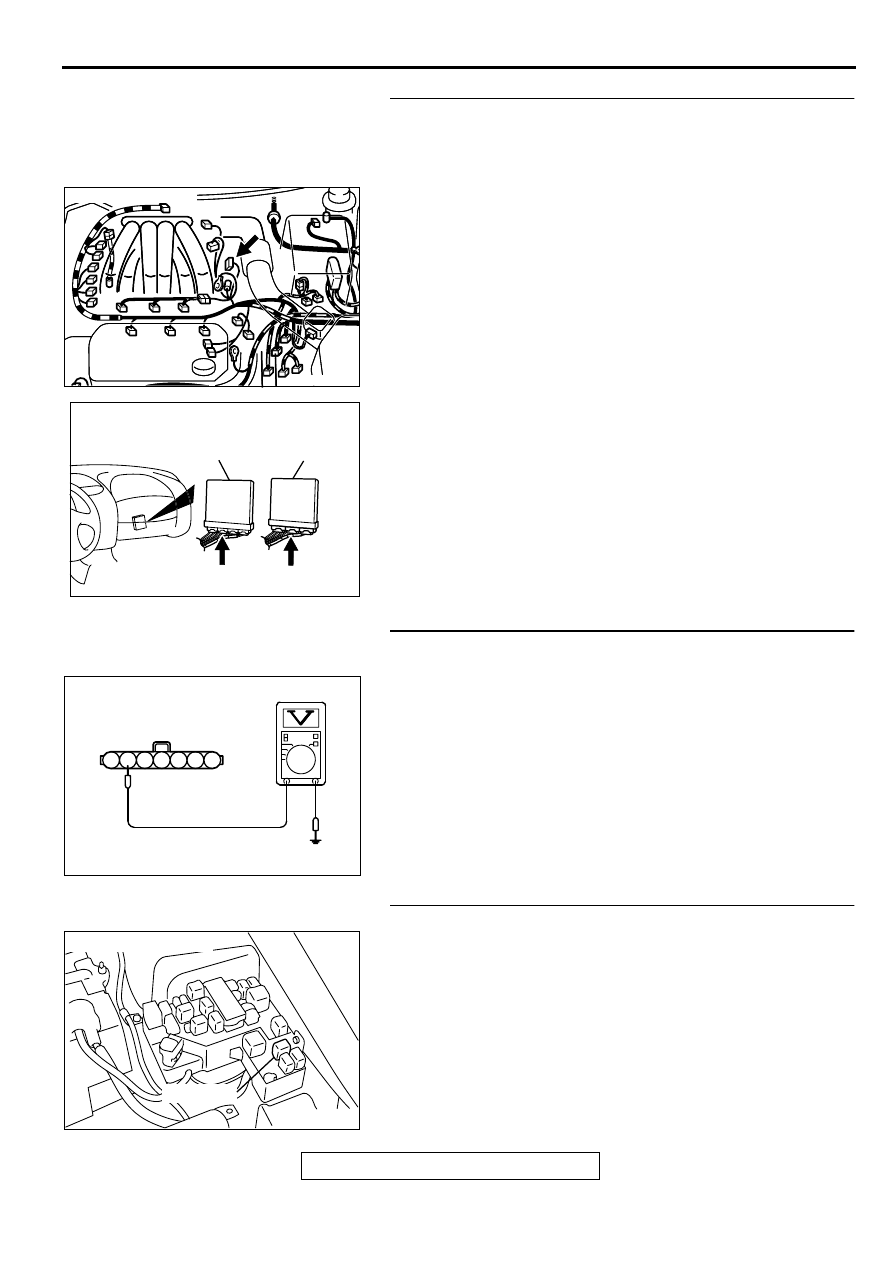
STEP 9. Check for short circuit to ground between
camshaft position sensor connector B-22 terminal 5 and
ECM connector C-58 terminal 50 <M/T> or PCM connector
C-55 terminal 56 <A/T>.
Q: Is the harness wire in good condition?
YES : Replace the ECM or PCM. Then go to Step 18.
NO : Repair it. Then go to Step 18.
STEP 10. Check the power supply voltage at camshaft
position sensor connector B-22.
(1) Disconnect the connector B-22 and measure at the harness
side.
(2) Turn the ignition switch to the "ON" position.
(3) Measure the voltage between terminal 6 and ground.
•
Voltage should be battery positive voltage.
(4) Turn the ignition switch to the "LOCK" (OFF) position.
Q: Is the voltage normal?
YES : Go to Step 12.
NO : Go to Step 11.
STEP 11. Check connector A-21X at MFI relay for damage.
Q: Is the connector in good condition?
YES : Repair harness wire between MFI relay connector A-
21X terminal 1 and camshaft position sensor
connector B-22 terminal 6 because of open circuit or
short circuit to ground. Then go to Step 18.
NO : Repair or replace it. Refer to GROUP 00E, Harness
Connector Inspection (
). Then go to Step 18.
AK000217AB
AK000217
CONNECTOR : B-22
AK000225
CONNECTOR : C-58<M/T>, C-55<A/T>
C-55
C-58
PCM<A/T>
ECM<M/T>
AI
AK000252AB
B-22 HARNESS
SIDE CONNECTOR
7 6 5 4 3 2 1
AK000226
AK000226AB
CONNECTOR : A-21X
MFI RELAY
MULTIPORT FUEL INJECTION (MFI) DIAGNOSIS
TSB Revision
MULTIPORT FUEL INJECTION (MFI) <3.0L ENGINE>
13B-264
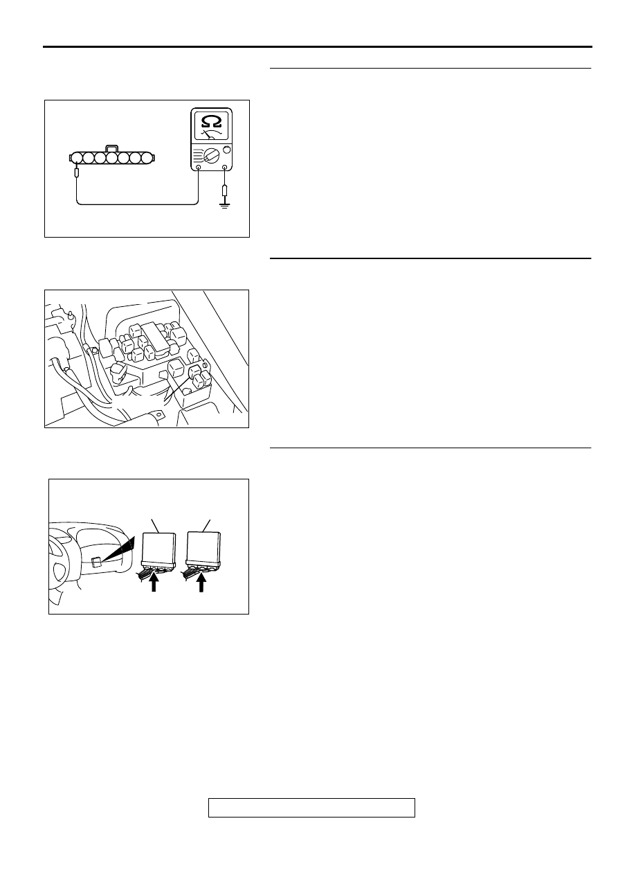
STEP 12. Check the continuity at camshaft position sensor
connector B-22.
(1) Disconnect the connector B-22 and measure at the harness
side.
(2) Check for the continuity between terminal 7 and ground.
•
Should be less than 2 ohm.
Q: Is the continuity normal?
YES : Go to Step 13.
NO : Repair harness wire between camshaft position
sensor connector B-22 terminal 7 and ground
because of open circuit or harness damage. Then go
to Step 18.
STEP 13. Check connector A-21X at the MFI relay for
damage.
Q: Is the connector in good condition?
YES : Go to Step 14.
NO : Repair or replace it. Refer to GROUP 00E, Harness
Connector Inspection (
). Then go to Step 18.
STEP 14. Check connector C-58 at ECM <M/T> or
connector C-55 at PCM <A/T> for damage.
Q: Is the connector in good condition?
YES : Go to Step 15.
NO : Repair or replace it. Refer to GROUP 00E, Harness
Connector Inspection (
). Then go to Step 18.
AK000253AB
B-22 HARNESS
SIDE CONNECTOR
7 6 5 4 3 2 1
AK000226
AK000226AB
CONNECTOR : A-21X
MFI RELAY
AK000225
CONNECTOR : C-58<M/T>, C-55<A/T>
C-55
C-58
PCM<A/T>
ECM<M/T>
AI
MULTIPORT FUEL INJECTION (MFI) DIAGNOSIS
TSB Revision
MULTIPORT FUEL INJECTION (MFI) <3.0L ENGINE>
13B-265
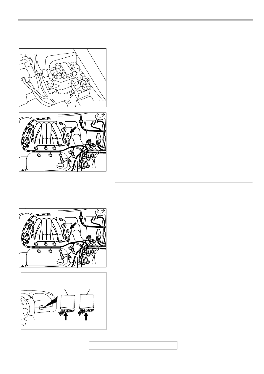
STEP 15. Check for harness damage between MFI relay
connector A-21X terminal 1 and camshaft position sensor
connector B-22 terminal 6.
Q: Is the harness wire in good condition?
YES : Go to Step 16.
NO : Repair it. Then go to Step 18.
STEP 16. Check for harness damage between camshaft
position sensor connector B-22 terminal 5 and ECM
connector C-58 terminal 50 <M/T> or PCM connector C-55
terminal 56 <A/T>.
Q: Is the harness wire in good condition?
YES : Go to Step 17.
NO : Repair it. Then go to Step 18.
AK000226
AK000226AB
CONNECTOR : A-21X
MFI RELAY
AK000217AB
AK000217
CONNECTOR : B-22
AK000217AB
AK000217
CONNECTOR : B-22
AK000225
CONNECTOR : C-58<M/T>, C-55<A/T>
C-55
C-58
PCM<A/T>
ECM<M/T>
AI
MULTIPORT FUEL INJECTION (MFI) DIAGNOSIS
TSB Revision
MULTIPORT FUEL INJECTION (MFI) <3.0L ENGINE>
13B-266
STEP 17. Check the camshaft position sensor vane.
Q: Is the vane in a good condition?
YES : Replace the camshaft position sensor. Then go to
Step 18.
NO : Repair it. Then go to Step 18.
STEP 18. Test the OBD-II drive cycle.
(1) Carry out a test drive with the drive cycle pattern. Refer to,
Procedure 6
−
Other Monitor (
).
(2) Check the diagnostic trouble code (DTC).
Q: Is the DTC P0340 is output?
YES : Retry the troubleshooting.
NO : The inspection is complete.
DTC P0401: Exhaust Gas Recirculation Flow Insufficient Detected
TECHNICAL DESCRIPTION
•
When the EGR solenoid switches from "OFF" to
"ON" while the engine is running, EGR gas flows.
•
The ECM <M/T> or PCM <A/T> checks how the
EGR gas flow signal changes.
DTC SET CONDITIONS
Check Conditions
•
At least twenty seconds have passed since the
last monitor was complete.
•
Engine coolant temperature is higher than 77
°
C
(141
°
F).
•
Engine speed is at between 1,000 and 1,650 <M/
T> or 910 and 1,650 <A/T> r/min.
•
Intake air temperature is higher than 5
°
C (41
°
F).
•
Barometric pressure is higher than 76 kPa (11
psi).
•
Vehicle speed is 5 km/h (3.1 mph) <M/T> or 30
km/h (18.7 mph) <A/T> or more.
•
At least ninety seconds have passed since
manifold differential pressure sensor output
voltage fluctuated 1.5 volts or more.
•
The throttle valve is closed.
•
Volumetric efficiency is lower than 18 <M/T> or
28 <A/T> percent.
•
Monitoring time: 2 seconds.
Judgement Criteria
•
The intake manifold pressure fluctuations are
minimal. When the EGR solenoid is turned ON.
•
Three monitors during one drive cycle
TROUBLESHOOTING HINTS (The most likely
causes for this code to be set are:)
•
EGR valve does not open.
•
EGR control vacuum is too low.
•
EGR solenoid failed.
•
Open or shorted EGR solenoid circuit, or loose
connector.
•
Manifold differential pressure sensor failed.
•
ECM failed. <M/T>
•
PCM failed. <A/T>
DIAGNOSIS
Required Special Tools
MB991502: Scan Tool (MUT-II)
STEP 1. Check the EGR system
Refer to GROUP 17, Emission Control System
−
Exhaust Gas
Recirculation (EGR) System - EGR System Check (
).
Q: Are there any abnormalities?
Нет комментариевНе стесняйтесь поделиться с нами вашим ценным мнением.
Текст