Mitsubishi Eclipse / Eclipse Spyder (2000-2002). Service and repair manual — part 540
FRONT AXLE HUB ASSEMBLY
TSB Revision
FRONT AXLE
26-9
INSPECTION
M1261001800093
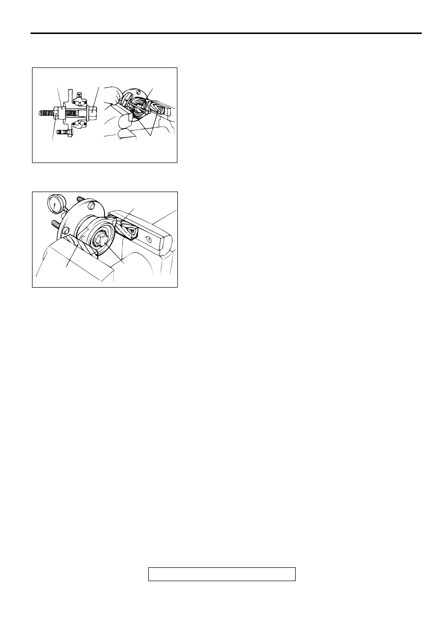
WHEEL BEARING BREAKAWAY TORQUE CHECK
1. Install the special tools MB990998 and MB990326 to the
front hub assembly and tighten the nut to the specified
torque.
Tightening torque: 226
±
29 N
⋅
m (167
±
21 ft-lb)
2. Measure the wheel bearing breakaway torque with special
tool MB990326.
Limit: 1.0 N
⋅
m (9 in-lb) or less
3. Wheel bearing breakaway torque must be under the limit
value and there should be no roughness when rotating the
hub.
WHEEL BEARING END PLAY CHECK
1. Install the special tool MB990998 to the front hub assembly
and tighten the nut to the specified torque.
Tightening torque: 226
±
29 N
⋅
m (167
±
21 ft-lb)
2. Measure the play in the hub axial direction.
Limit: 0.05 mm (0.002 inch)
3. If the play exceeds the limit, replace the front hub assembly.
AC001152
MB990998
BOLT
MB990326
WOOD
BLOCK
226 ± 29 N·m
167 ± 21 ft-lb
AB
AC001153
WOOD
BLOCK
WOOD
BLOCK
BOLT
AB
KNUCKLE
TSB Revision
FRONT AXLE
26-10
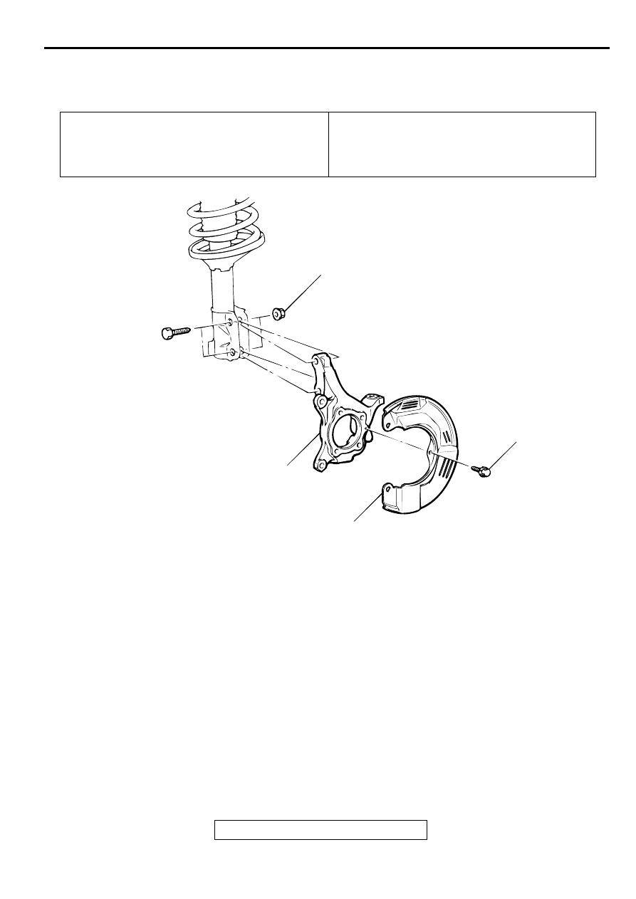
K N U C K LE
REMOVAL AND INSTALLATION
M1261002400076
INSPECTION
M1261002500062
Check the knuckle surface for galling and cracks.
Pre-removal Operation
•
Front Hub Assembly Removal (Refer to
Post-installation Operation
•
Front Hub Assembly Installation (Refer to
•
Wheel Alignment Check and Adjustment (Refer to
GROUP 33A, On-vehicle Service
−
Front Wheel Align-
ment Check and Adjustment
.)
AC001154
300 ± 24 N·m
221 ± 18 ft-lb
8.9 ± 1.9 N·m
78 ± 17 in-lb
2
1
AB
REMOVAL STEPS
1.
DUST SHIELD
2.
KNUCKLE
DRIVE SHAFT ASSEMBLY
TSB Revision
FRONT AXLE
26-11
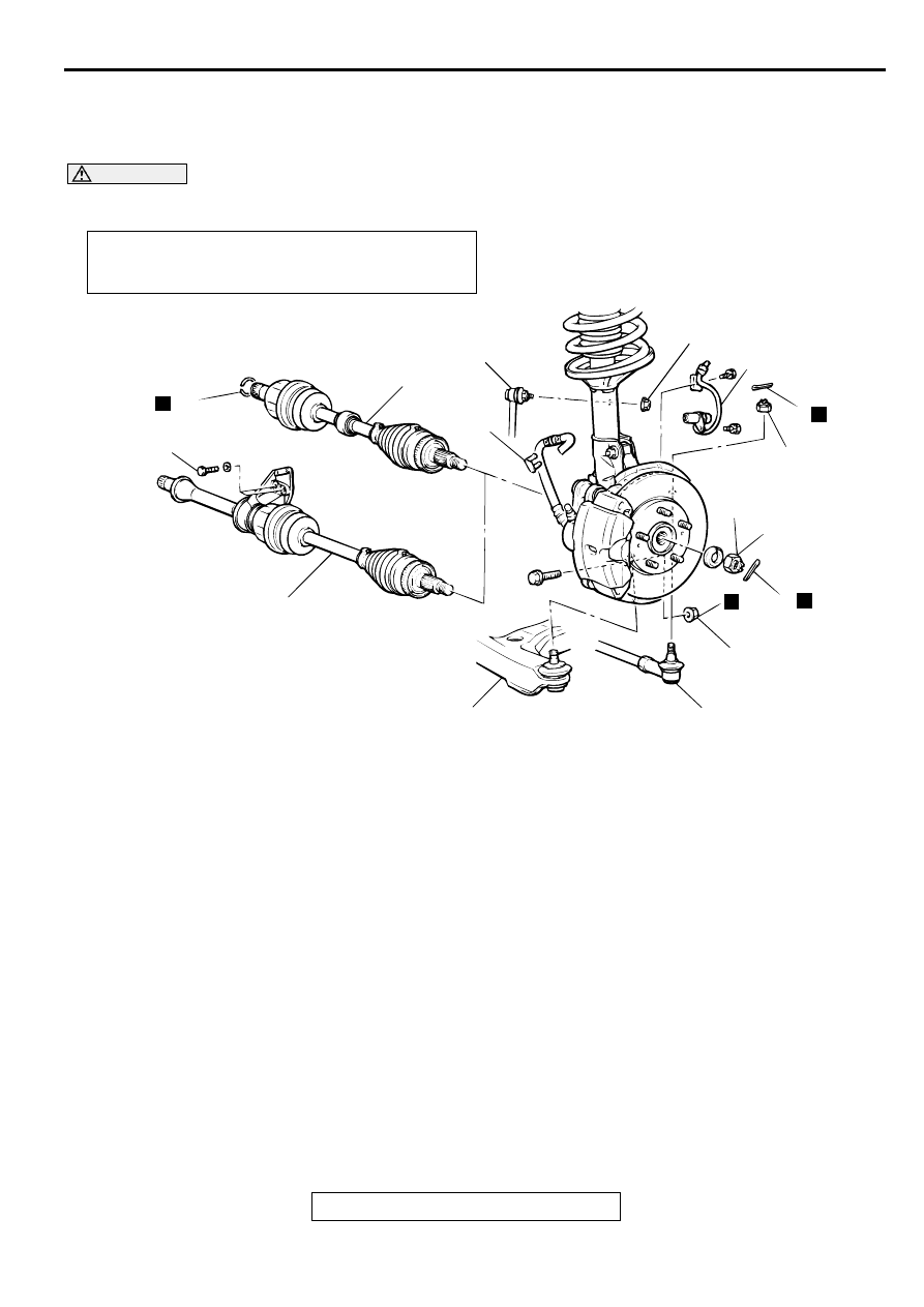
D R IVE SH A FT ASSEM BLY
REMOVAL AND INSTALLATION
M1261003500087
CAUTION
For vehicles with ABS, be careful when handling the projection at the tip of the speed sensor so as
not to damage it by striking against other parts.
Required Special Tools:
•
MB990242: Puller Bar
•
MB990767: End Yoke Holder
•
MB990998: Front Hub Remover and Installer
•
MB991113 or MB990635: Steering Linkage Puller
•
MB991354: Puller Body
Post-installation Operation
•
Press Dust Cover with a Finger to Check for Crack or
Damage in Ball Joint Dust Cover.
AC001155
<2.4L ENGINE, 3.0L ENGINE-LH>
N
11
40 ± 5 N·m
30 ± 3 ft-lb
<3.0L ENGINE-RH>
10
9
8
2
44 ± 10 N·m
33 ± 7 ft-lb
1
N
6
29 ± 4 N·m
21 ± 3 ft-lb
4
226 ± 29 N·m
167 ± 21 ft-lb
N
3
N
108 ± 10 N·m
80 ± 7 ft-lb
7
5
AB
REMOVAL STEPS
1.
SPEED SENSOR CABLE
CONNECTION <VEHICLES
WITH ABS>
2.
BRAKE HOSE CLIP
3.
COTTER PIN
<<A>>
>>B<<
4.
DRIVESHAFT NUT
<<B>>
5.
LOWER ARM BALL JOINT
CONNECTION
6.
COTTER PIN
<<B>>
7.
TIE ROD END CONNECTION
8.
STABILIZER LINK CONNECTION
<<C>>
>>A<<
9.
DRIVESHAFT
<<C>>
>>A<<
10. DRIVESHAFT AND INNER
SHAFT
11. CIRCLIP
REMOVAL STEPS (Continued)
DRIVE SHAFT ASSEMBLY
TSB Revision
FRONT AXLE
26-12
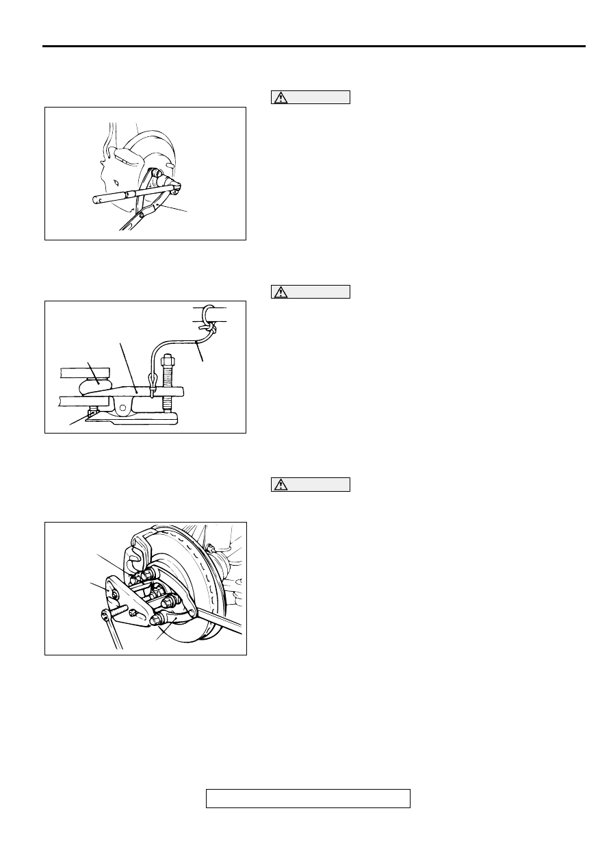
REMOVAL SERVICE POINTS
<<A>> DRIVESHAFT NUT REMOVAL
CAUTION
Do not apply pressure to the wheel bearing by the vehicle
weight to avoid possible damage when the driveshaft nut
is loosened.
Use special tool MB990787 to fix the hub and remove the
driveshaft nut.
<<B>> LOWER ARM BALL JOINT/TIE ROD END
DISCONNECTION
CAUTION
•
Do not remove the nut from the ball joint. Loosen it and
use special tool MB991113 or MB990635 to avoid
possible damage to the ball joint threads.
•
Hang special tool MB991113 or MB990635 with rope or
wire to prevent them from falling.
Use special tool MB991113 or MB990635 to disconnect the
lower arm ball joint or the tie rod end from the knuckle.
<<C>> DRIVESHAFT/DRIVESHAFT AND INNER SHAFT
REMOVAL
CAUTION
Do not damage the ABS rotor attached to the BJ outer race
<Vehicles with ABS>.
1. Use special tools MB991354, MB990242 and MB990767 to
push the driveshaft out from the hub.
AC001150AB
MB990767
ACX00715AC
BALL JOINT
CORD
NUT
MB991113 OR
MB990635
AC001156
MB990242
(THREE)
MB990767
AB
MB991354
Нет комментариевНе стесняйтесь поделиться с нами вашим ценным мнением.
Текст