Mitsubishi Eclipse / Eclipse Spyder (2000-2002). Service and repair manual — part 539
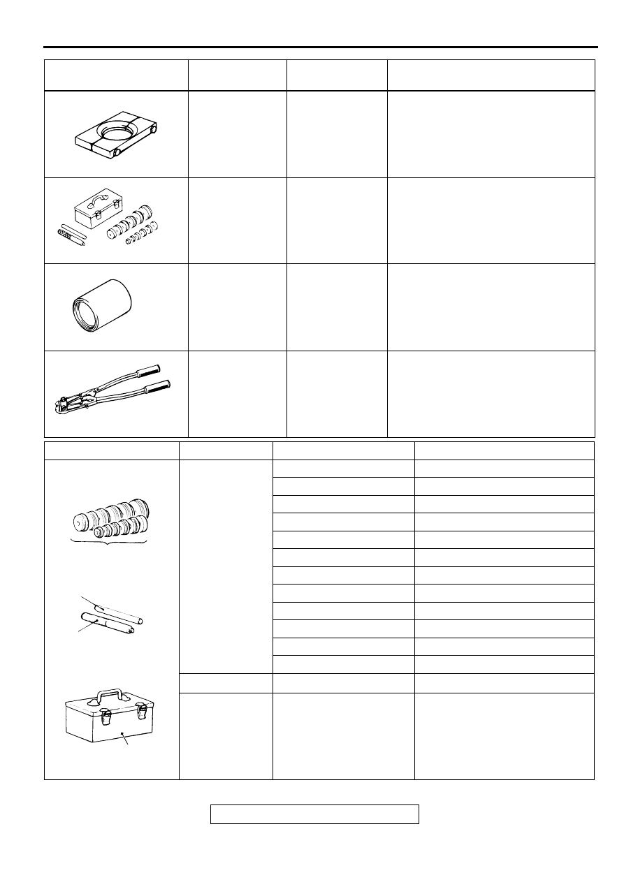
SPECIAL TOOLS
TSB Revision
FRONT AXLE
26-5
MB991248 or
MB998801
Inner shaft
remover
MD998348-01
Inner shaft removal
MB990925
Bearing and oil
seal installer set
MB990925-01 or
General service
tool
Bearing removal and dust seal
installation
MB990890
Rear suspension
bush base
MB990890-01
Oil seal installation
MB991561
Boot band
crimping tool
MB991561
Resin boot band installation
TOOL
TOOL NUMBER
AND NAME
SUPERSESSION APPLICATION
MB991248
MB990925
MB990890
MB991561
TOOL
TYPE
TOOL NUMBER
O D mm (in)
A
MB990926
39.0 (1.54)
MB990927
45.0 (1.77)
MB990928
49.5 (1.95)
MB990929
51.0 (2.00)
MB990930
54.0 (2.13)
MB990931
57.0 (2.24)
MB990932
61.0 (2.40)
MB990933
63.5 (2.50)
MB990934
67.5 (2.66)
MB990935
71.5 (2.81)
MB990936
75.5 (2.97)
MB990937
79.0 (3.11)
B
MB990938
−
C
MB990939
−
ACX02372
A
B
C
BRASS BAR
BAR (SNAP-IN TYPE)
TOOL BOX
MB990925
AB
INSTALL ADAPTER
ON-VEHICLE SERVICE
TSB Revision
FRONT AXLE
26-6
O N -VEH IC LE SERVIC E
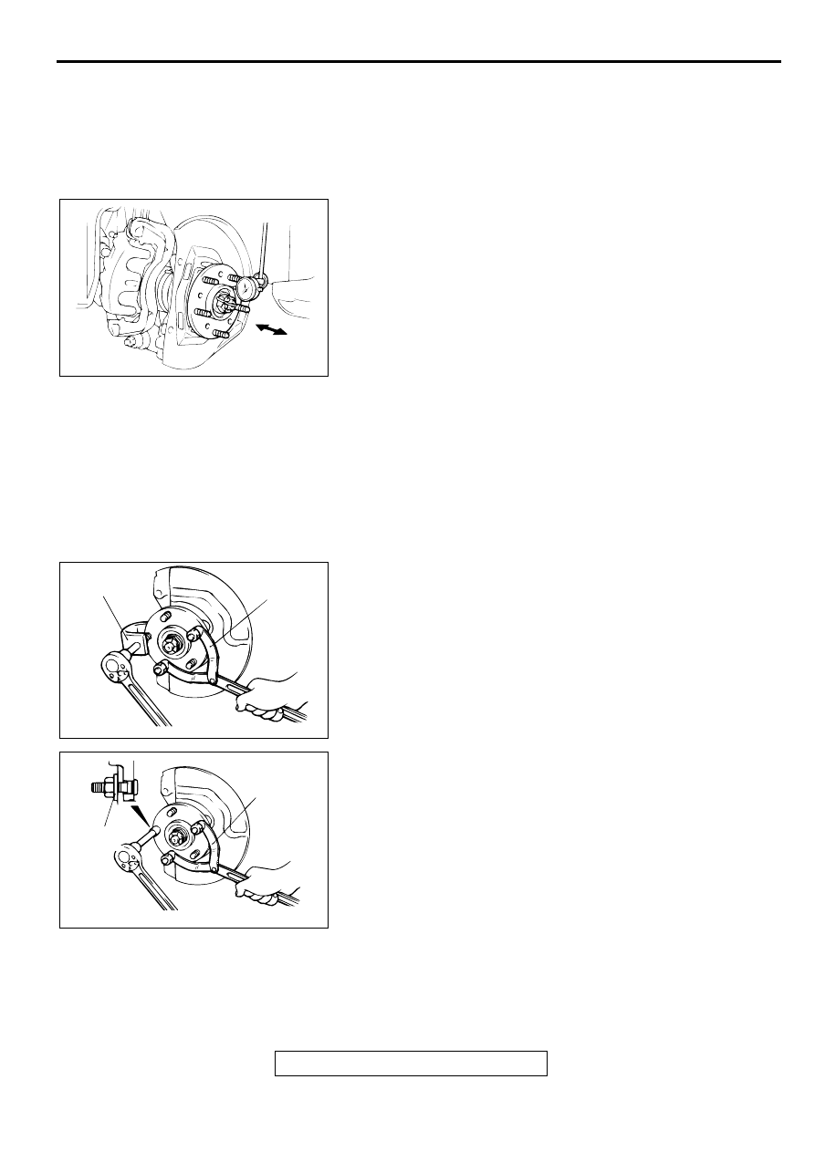
HUB END PLAY CHECK
M1261000900075
1. Remove the disc brake caliper and suspend it with a wire.
2. Remove the brake disc from the front hub.
3. Attach a dial gauge as shown in the illustration, and then
measure the end play while moving the hub in the axial
direction.
Limit: 0.05 mm (0.002 inch)
4. If end play exceeds the limit, replace the front hub assembly.
HUB BOLT REPLACEMENT
M1261001000086
Required Special Tools:
•
MB990767: End Yoke Holder
•
MB991618: Hub Bolt Remover
1. Remove the caliper assembly and suspend it with wire so
that it does not fall.
2. Remove the brake disc.
3. Use the special tools MB990767 and MB991618 to remove
the hub bolts.
4. Install the plain washer to the new hub bolt, and install the
bolt with a nut.
AC001146
AC001147
MB990767
AB
MB991618
AC001148
MB990767
AB
PLAIN
WASHER
FRONT AXLE HUB ASSEMBLY
TSB Revision
FRONT AXLE
26-7
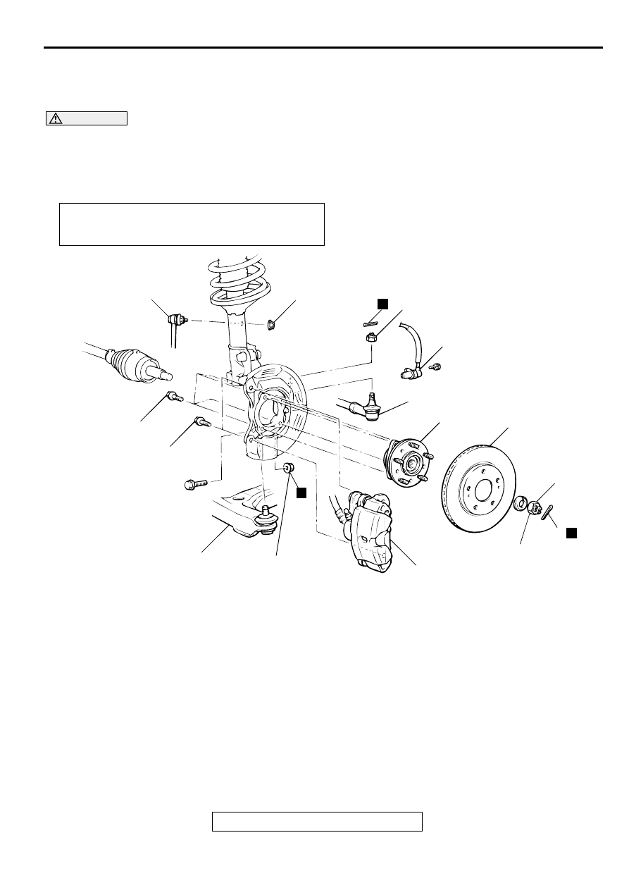
FR O N T A XLE H U B A SSEM B LY
REMOVAL AND INSTALLATION
M1261001700074
CAUTION
•
For vehicles with ABS, be careful when handling the projection at the tip of the speed sensor so
as not to damage it by striking against other parts.
•
The front hub assembly should not be disassembled. When removing the front hub assembly, the
wheel bearing inner race may be left at the spindle side. In this case, always replace the front hub
assembly, otherwise the hub will damage the oil seal, causing oil leaks or excessive play.
Required Special Tools:
•
MB990326: Preload Socket
•
MB990767: End Yoke Holder
•
MB990998: Front Hub Remover and Installer
•
MB991113 or MB990635: Steering Linkage Puller
Post-installation Operation
•
Press Dust Cover with a Finger to Check for Crack or
Damage in Ball Joint Dust Cover.
AC001149
N
7
44 ± 10 N·m
33 ± 7 ft-lb
N
N
29 ± 4 N·m
21 ± 4 ft-lb
1
6
9
3
5
4
226 ± 29 N·m
167 ± 21 ft-lb
2
108 ± 10 N·m
80 ± 7 ft-lb
8
88 ± 10 N·m
65 ± 7 ft-lb
100 ± 10 N·m
74 ± 7 ft-lb
AB
REMOVAL STEPS
1. FRONT SPEED SENSOR
<VEHICLES WITH ABS>
<<A>>
2. CALIPER ASSEMBLY
3. BRAKE DISC
4. COTTER PIN
<<B>>
>>A<<
5. DRIVESHAFT NUT
<<C>>
6. TIE ROD END CONNECTION
7. STABILIZER LINK CONNECTION
<<C>>
8. LOWER ARM ASSEMBLY
CONNECTION
9. FRONT HUB ASSEMBLY
REMOVAL STEPS (Continued)
FRONT AXLE HUB ASSEMBLY
TSB Revision
FRONT AXLE
26-8
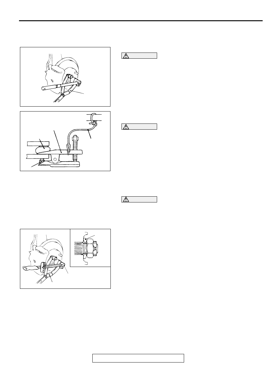
REMOVAL SERVICE POINTS
<<A>> CALIPER ASSEMBLY REMOVAL
Secure the removed caliper assembly with wire, etc.
<<B>> DRIVESHAFT NUT REMOVAL
CAUTION
Do not apply pressure to wheel bearing by the vehicle
weight to avoid possible damage when driveshaft nut is
loosened.
Use special tool MB990787 to fix the hub and remove the
driveshaft nut.
<<C>> TIE ROD END/LOWER ARM ASSEMBLY
DISCONNECTION
CAUTION
•
Do not remove the nut from ball joint. Loosen it and use
special tool MB991113 or MB990635 to avoid possible
damage to ball joint threads.
•
Hang special tool MB991113 or MB990635 with rope or
wire to prevent them from falling.
Use special tool MB991113 or MB990635 to disconnect the tie
rod end or lower arm assembly from the knuckle.
INSTALLATION SERVICE POINT
>>A<< DRIVE SHAFT NUT INSTALLATION
CAUTION
Do not apply pressure to wheel bearing by the vehicle
weight to avoid possible damage before securely
tightening the driveshaft nut.
1. Face the flat side of a washer to a driveshaft nut to install
2. Use special tool MB990767 to fix the hub and tighten the
driveshaft nut.
3. If the position of the cotter pin holes does not match, tighten
the nut up to 255 N
⋅
m (188 ft-lb) maximum.
4. Install the cotter pin in the first matching holes and bend it
securely.
AC001150AB
MB990767
ACX00715AC
BALL JOINT
CORD
NUT
MB991113 OR
MB990635
AC001151
WASHER
MB990767
226 ± 29 N·m
167 ± 21 ft-lb
AB
Нет комментариевНе стесняйтесь поделиться с нами вашим ценным мнением.
Текст