Mitsubishi Eclipse / Eclipse Spyder (2000-2002). Service and repair manual — part 302
MULTIPORT FUEL INJECTION (MFI) DIAGNOSIS
TSB Revision
MULTIPORT FUEL INJECTION (MFI) <3.0L ENGINE>
13B-407
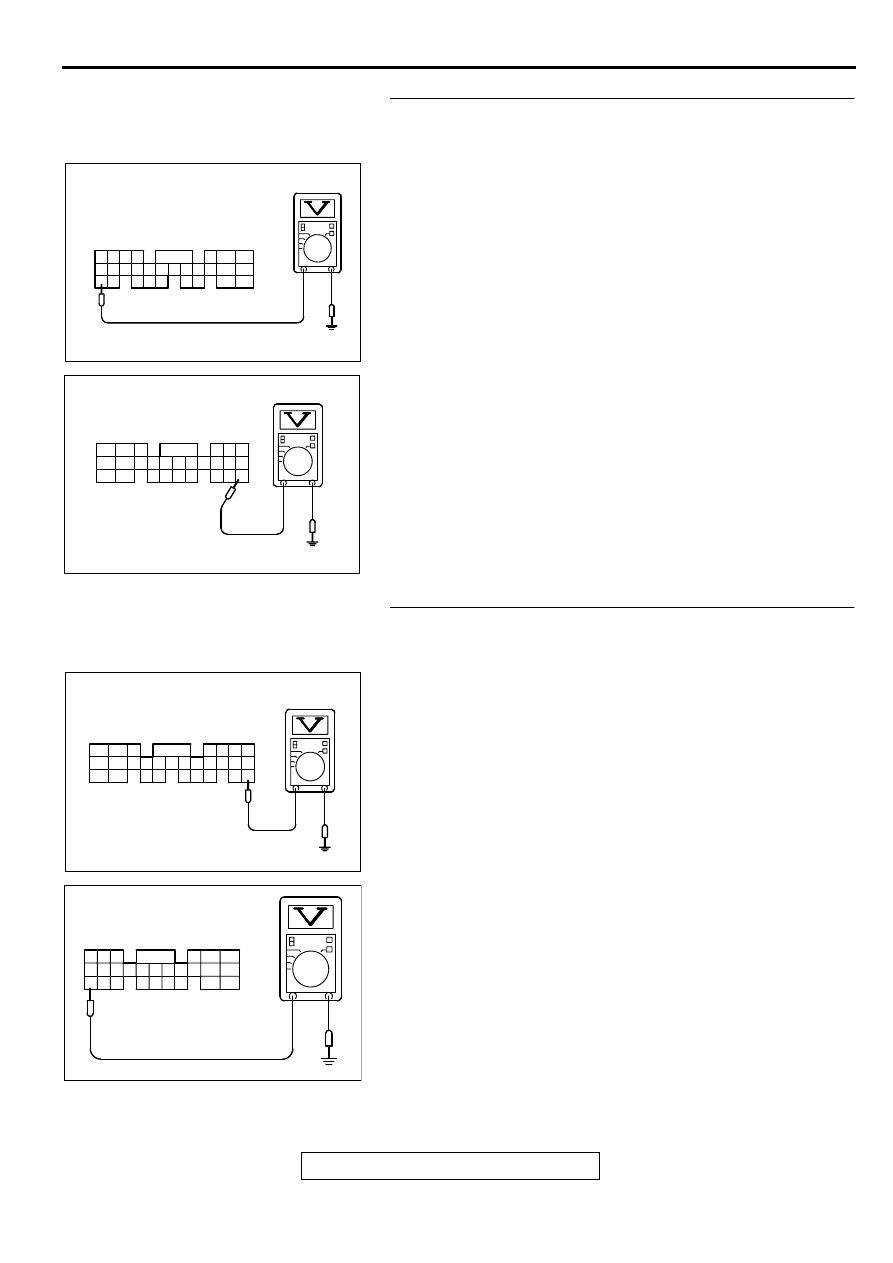
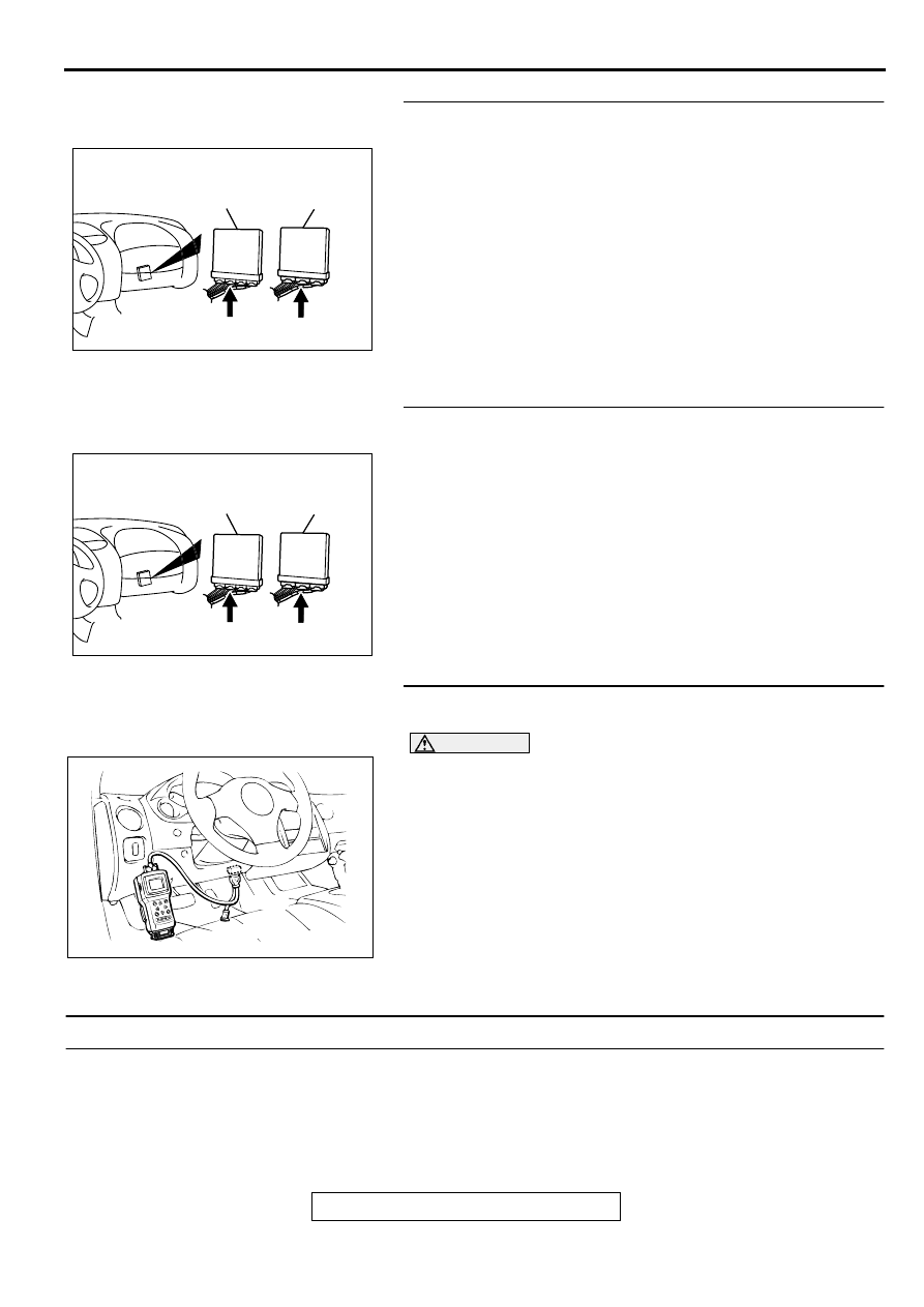
STEP 3. Check the backup power supply voltage at ECM
connector C-58 <M/T> or PCM connector C-55 <A/T> by
backprobing.
(1) Do not disconnect the ECM connector C-58 <M/T> or PCM
connector C-55 <A/T>.
(2) Measure the voltage between terminal 60 <M/T> or 66 <A/
T> and ground by backprobing.
•
Voltage should be battery positive voltage.
Q: Is the voltage normal?
YES : Go to Step 6.
NO : Go to Step 4.
STEP 4. Check the backup power supply voltage at ECM
harness side connector C-58 <M/T> or PCM harness side
connector C-55 <A/T>.
(1) Disconnect the ECM connector C-58 <M/T> or PCM
connector C-55 <A/T> and measure at the harness side.
(2) Measure the voltage between terminal 60 <M/T> or 66 <A/
T> and ground.
•
Voltage should be battery positive voltage.
Q: Is the voltage normal?
YES : Go to Step 5.
NO : Check connectors C-28, C-78 and C-89 at
intermediate connector for damage, and repair or
replace as required. Refer to GROUP 00E, Harness
Connector Inspection (
). If intermediate
connector are in good condition, repair harness wire
between battery and ECM connector C-58 <M/T>
terminal 60 or PCM connector C-55 <A/T> terminal 66
because of open circuit or short circuit to ground.
Then go to Step 7.
AK000738
41424344
48
50 51
49
52 5354555657 58 59
45 46 47
60 61
626364
65
67 68
66
AK000738 AB
C-58 CONNECTOR
HARNESS SIDE VIEW
<M/T>
AK000731
C-55 CONNECTOR
HARNESS SIDE VIEW
46
57
66
45
56
65
44
55
43
49
54
64
42
48
59
41
47
58
53
63
52
62
51
61
50
60
AD
<A/T>
AK000374AC
47 46 45
41
42
43
44
48
49
50
51
52
53
54
55
56
57
58
59
60
61
62
63
64
65
66
67
68
<M/T>
C-58 HARNESS
SIDE CONNECTOR
AKX01436
41
42
43
44
45
46
57 56 55 54 53 52
48 47
58
59
60
61
62
66 65 64
63
51 50 49
C-55 HARNESS
SIDE CONNECTOR
AG
<A/T>
MULTIPORT FUEL INJECTION (MFI) DIAGNOSIS
TSB Revision
MULTIPORT FUEL INJECTION (MFI) <3.0L ENGINE>
13B-408
STEP 5. Check connector C-58 at ECM <M/T> or connector
C-55 at PCM <M/T> for damage.
Q: Is the harness connector in good condition?
YES : Check connectors C-28, C-78 and C-89 at
intermediate connector for damage, and repair or
replace as required. Refer to GROUP 00E, Harness
Connector Inspection (
). If intermediate
connector are in good condition, repair harness wire
between battery and ECM connector C-58 <M/T>
terminal 60 or PCM connector C-55 <A/T> terminal 66
because of open circuit or short circuit to ground.
Then go to Step 7.
NO : Repair or replace it. Refer to GROUP 00E, Harness
Connector Inspection (
). Then go to Step 7.
STEP 6. Check connector C-58 at ECM <M/T> or connector
C-55 at PCM <M/T> for damage.
Q: Is the harness connector in good condition?
YES : Replace the PCM. Then go to Step 7.
NO : Repair or replace it. Refer to GROUP 00E, Harness
Connector Inspection (
). Then go to Step 7.
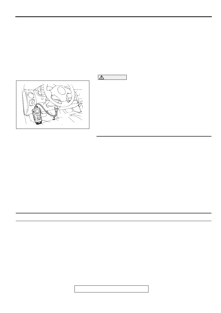
STEP 7. Using scan tool MB991502, read the diagnostic
trouble code (DTC).
CAUTION
To prevent damage to scan tool MB991502, always turn the
ignition switch to the "LOCK" (OFF) position before
connecting or disconnecting scan tool MB991502.
(1) Connect scan tool MB991502 to the data link connector.
(2) Turn the ignition switch to the "ON" position.
(3) Read the DTC.
(4) Turn the ignition switch to the "LOCK" (OFF) position.
Q: Is the DTC P1603 is output?
YES : Retry the troubleshooting.
NO : The inspection is complete.
DTC P1610: Immobilizer Malfunction
TECHNICAL DESCRIPTION
•
ECM <M/T> or PCM <A/T> monitors the
communication condition with the immobilizer-
ECU and the message from the immobilizer-
ECU, and when the abnormality is found, ECM
<M/T> or PCM <A/T> makes the engine not to
start.
DTC SET CONDITIONS
Check Conditions
•
Ignition switch: ON
AK000225
CONNECTOR : C-58<M/T>, C-55<A/T>
C-55
C-58
PCM<A/T>
ECM<M/T>
AI
AK000225
CONNECTOR : C-58<M/T>, C-55<A/T>
C-55
C-58
PCM<A/T>
ECM<M/T>
AI
AKX01177
16 PIN
MB991502
AB
MULTIPORT FUEL INJECTION (MFI) DIAGNOSIS
TSB Revision
MULTIPORT FUEL INJECTION (MFI) <3.0L ENGINE>
13B-409
Judgment Criteria
•
When the communication error between ECM
<M/T> or PCM <A/T> and the immobilizer-ECU
continues for 2 seconds or more.
•
When ECM <M/T> or PCM <A/T> receives the
communication of prohibition for starting from the
immobilizer-ECU.
TROUBLESHOOTING HINTS (The most likely
causes for this code to be set are:)
•
Malfunction of harness or connector.
•
Malfunction of immobilizer-ECU.
•
Malfunction of ECM <M/T> or PCM <A/T>.
DIAGNOSIS
Required Special Tools
MB991502: Scan Tool (MUT-II)
CAUTION
To prevent damage to scan tool MB991502, always turn the
ignition switch to the "LOCK" (OFF) position before
connecting or disconnecting scan tool MB991502.
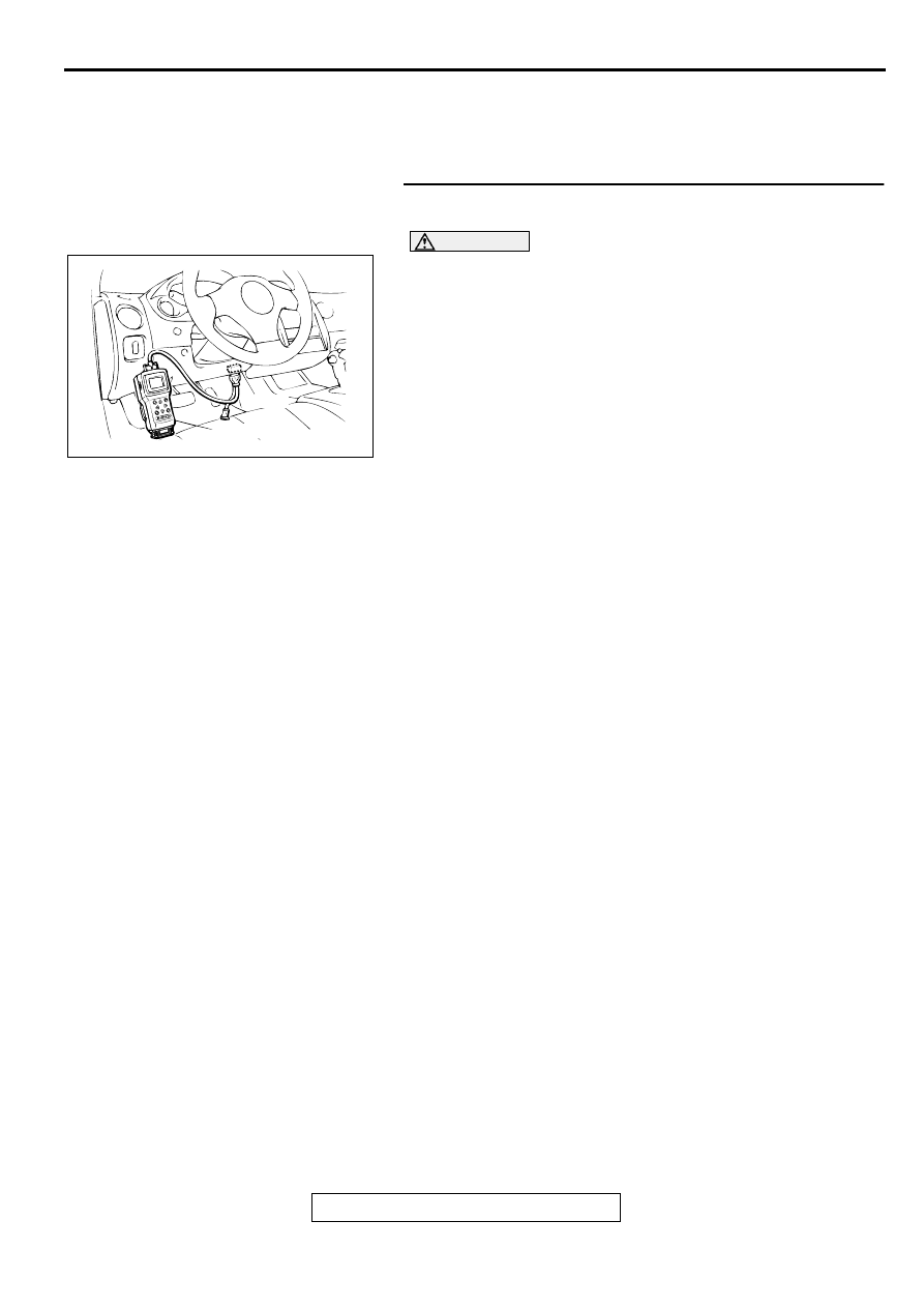
STEP 1. Using scan tool MB991502, read the immobilizer
diagnostic trouble code (DTC).
(1) Connect scan tool MB991502 to the data link connector.
(2) Turn the ignition switch to the "ON" position.
(3) Read the immobilizer system-DTC
(4) Turn the ignition switch to the "LOCK" (OFF) position.
Q: Is the immobilizer system-DTC is output?
YES : Refer to GROUP 54A, Ignition Switch and
Immobilizer System
−
Diagnostic Trouble Code Chart.
NO : If DTC P1610 is output again after the MFI-DTC has
been erased, replace the ECM <M/T> or PCM <A/T>.
Then check that the DTC P1610 does not reset.
DTC P1751: A/T Control Relay Malfunction
TECHNICAL DESCRIPTION
•
When a malfunction of the A/T control relay is
detected, the transaxle control CPU inside the
powertrain control module (PCM) outputs a
malfunction signal to the engine control CPU
inside the PCM.
DTC SET CONDITIONS
Check Conditions, Judgment Criteria
•
A/T control relay failure signal is input to the
engine control CPU from the transaxle control
CPU.
TROUBLESHOOTING HINTS (The most likely
causes for this code to be set are:)
•
A/T control relay failed.
•
Open or shorted A/T control relay circuit, or loose
connector.
•
PCM failed.
AKX01177
16 PIN
MB991502
AB
MULTIPORT FUEL INJECTION (MFI) DIAGNOSIS
TSB Revision
MULTIPORT FUEL INJECTION (MFI) <3.0L ENGINE>
13B-410
DIAGNOSIS
Required Special Tools
MB991502: Scan Tool (MUT-II)
STEP 1. Using scan tool MB991502, read the A/T
diagnostic trouble code (DTC).
CAUTION
To prevent damage to scan tool MB991502, always turn the
ignition switch to the "LOCK" (OFF) position before
connecting or disconnecting scan tool MB991502.
(1) Connect scan tool MB991502 to the data link connector.
(2) Turn the ignition switch to the "ON" position.
(3) Check the A/T-DTC.
(4) Turn the ignition switch to the "LOCK" (OFF) position.
Q: Is the A/T-DTC is output?
YES : Refer to GROUP 23A, Automatic Transaxle
Diagnosis
−
Diagnostic Trouble Code Chart (
NO : If DTC P1751 is output again after the MFI-DTC has
been erased, replace the PCM. Then check that the
DTC P1751 does not reset.
AKX01177
16 PIN
MB991502
AB
Нет комментариевНе стесняйтесь поделиться с нами вашим ценным мнением.
Текст