Mitsubishi Eclipse / Eclipse Spyder (2000-2002). Service and repair manual — part 303
MULTIPORT FUEL INJECTION (MFI) DIAGNOSIS
TSB Revision
MULTIPORT FUEL INJECTION (MFI) <3.0L ENGINE>
13B-411
SYMPTOM PROCEDURES
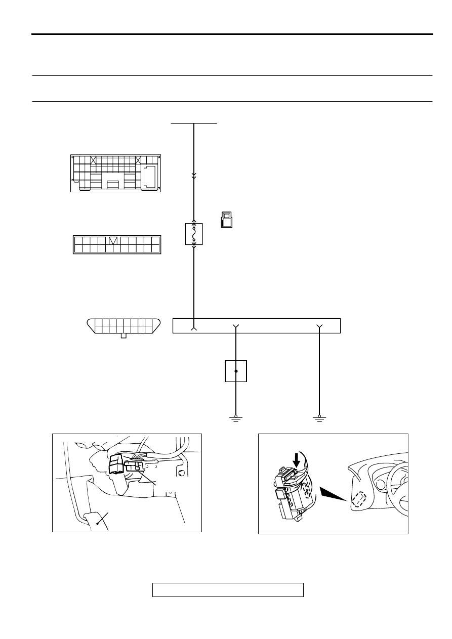
INSPECTION PROCEDURE 1: Communication with Scan Tool Is Not Possible. (Comunication with All
Systems Is Not Possible.)
AK000673
15
14
13
12
11
10
1 2 3 4 5 6 7 8
9
16
1
1
6
4
5
11
10
12 13
15
17
16
14
19
18
8 9
7
20
2
15 16
26 27 28 29
32 33 34
17 18 19 20 21 22 23 24 25
30 31
36 37
35
38
10
11 12 13
1 2 3
4 5 6 7 8 9
14
3
RED
RED
RED-BLA
CK
BLA
CK
BLA
CK
BLA
CK
FUSIBLE LINK(2)
C-89
C-110
C-104
MU801457
C-29
DATA LINK
CONNECTOR
38
1
18
16
JOINT
GROUND
POINT
4
5
JUNCTION
BLOCK
ACX02447
CONNECTOR:C-29
ACCELERATOR
PEDAL
DATA LINK
CONNECTOR
AI
AK000355 AC
CONNECTOR:C-110
MULTIPORT FUEL INJECTION (MFI) DIAGNOSIS
TSB Revision
MULTIPORT FUEL INJECTION (MFI) <3.0L ENGINE>
13B-412
CIRCUIT OPERATION
•
A battery positive voltage is applied on the data
link connector power terminal (terminal 16). The
ground terminals (terminal 4, 5) are grounded to
the vehicle body.
COMMENT
•
The cause is probably a defect in power supply
system (including ground) for the on-board
diagnostic test mode line.
TROUBLESHOOTING HINTS (The most likely
causes for this case:)
•
Malfunction of the data link connector.
•
Damaged harness wire.
DIAGNOSIS
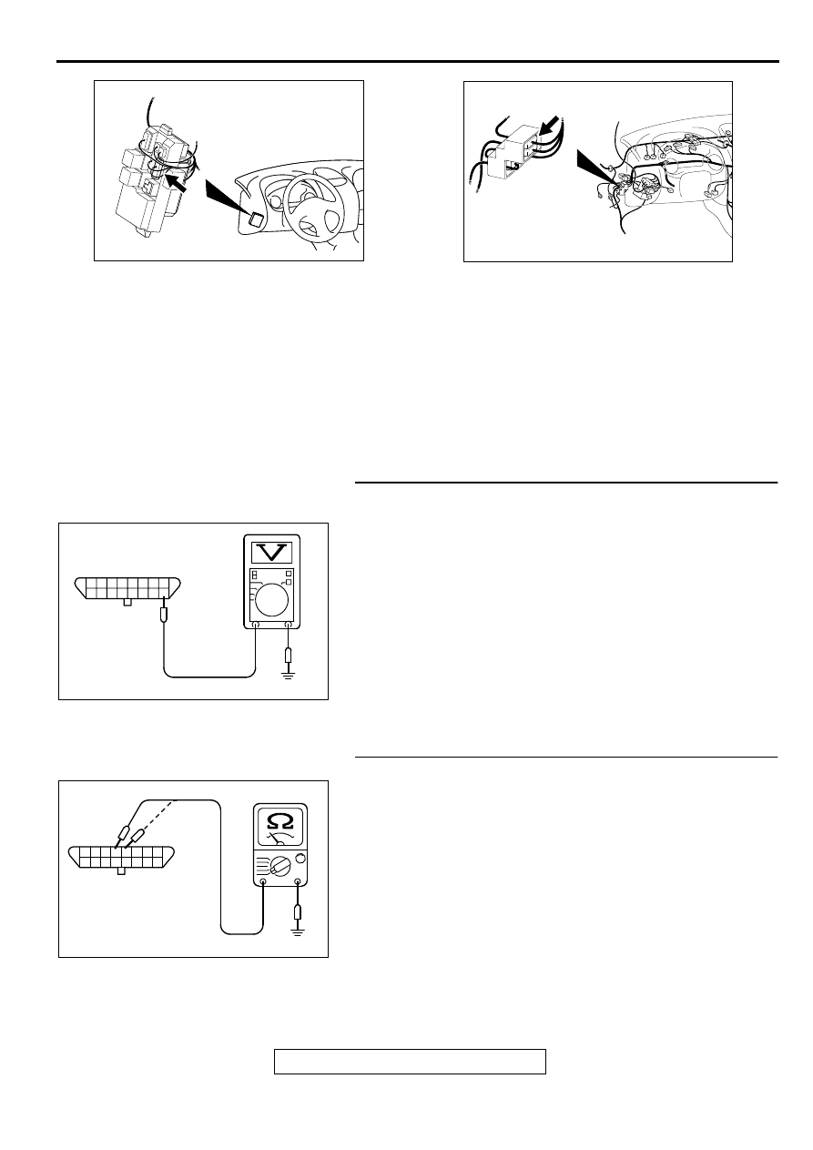
STEP 1. Check the power supply voltage at data link
connector C-29.
(1) Measure voltage between terminal 16 and ground.
•
Voltage should be battery positive voltage.
Q: Is the voltage normal?
YES : Go to step 2.
NO : Check harness connectors C-104, C-110 and C-89 at
intermediate connector for damage, and repair or
replace as required. Refer to GROUP 00E, Harness
Connector Inspection (
). If intermediate
connectors are in good condition, repair harness wire
between fusible link (2) and data link connector C-29
terminal 16 because of open circuit. Then confirm that
the malfunction symptom is eliminated.
STEP 2. Check the continuity at data link connector C-29.
(1) Check for the continuity between terminal 4, 5 and ground.
•
Should be less than 2 ohm.
Q: Is the continuity normal?
YES : Replace the scan tool. Then confirm that the
malfunction symptom is eliminated.
NO : Repair harness wire between data link connector C-
29 terminal 4, 5 and ground because of open circuit or
harness damage. Then confirm that the malfunction
symptom is eliminated.
AK000311
AK000311
CONNECTOR:C-104
AC
AK000345AE
CONNECTOR:C-89
AKX01430AF
1 2 3 4 5 6 7 8
9 10 111213141516
C-29 HARNESS
SIDE CONECTOR
AKX01431AE
1 2 3 4 5 6 7 8
9 10 111213141516
C-29 HARNESS
SIDE CONECTOR
MULTIPORT FUEL INJECTION (MFI) DIAGNOSIS
TSB Revision
MULTIPORT FUEL INJECTION (MFI) <3.0L ENGINE>
13B-413
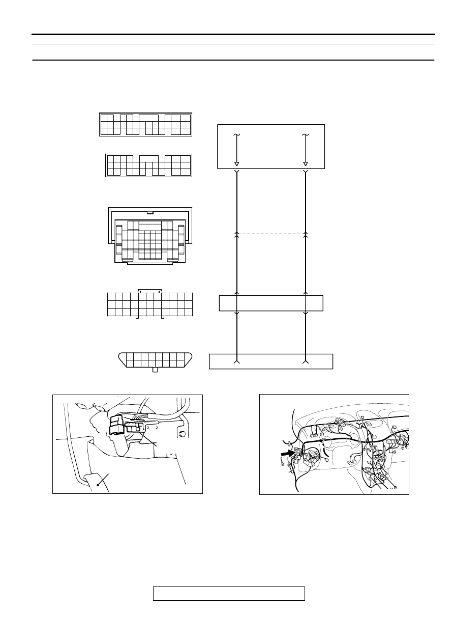
INSPECTION PROCEDURE 2: Scan Tool Communication with ECM or PCM Is Not Possible.
AK000711
GRA
Y
-
RED
GRA
Y
-
RED
GRA
Y
-
RED
RED-
WHITE
RED-
WHITE
RED-
WHITE
ENGINE CONTROL
MODULE(ECM)<M/T>
OR
POWERTRAIN CONTROL
MODULE(PCM)<A/T>
JOINT
CONNECTOR(1)
DATA LINK
CONNECTOR
1
11
8
9
10
12
15
7
84
85
C-28
7 8
5
3 4
35
34
10 11 12
2122 23 24
13 14 15
25 26 27
16
28
17
18 19 20
29
30 31
32 33
36 37
38
9
1 2
6
C-77
16
15
18
17
14
20
22
21
9
7
1 2
5
19
3
33
32
30 31
29
28
25
24
23
27
26
6
11
13
4
10
8
12
C-29
15
14
13
12
11
10
1 2 3 4 5 6 7 8
9
16
98
78
71
88 89
76 77
72
79
91
73
80
74
75
81
92
82 83
93
84 85
94
86 87
95 96
90
80
87
81
94
85
82
84
93
86
98
99
74
92
73
83
88
91
95
97
96
100
89
78
71
90
76 77
75
72
79
97
C-62<M/T>
(MU803783)
C-59<A/T>
(MU803782)
ACX02447
CONNECTOR:C-29
ACCELERATOR
PEDAL
DATA LINK
CONNECTOR
AI
AK000312AH
CONNECTOR:C-77
MULTIPORT FUEL INJECTION (MFI) DIAGNOSIS
TSB Revision
MULTIPORT FUEL INJECTION (MFI) <3.0L ENGINE>
13B-414
CIRCUIT OPERATION
•
A diagnostic output is made from the ECM
(terminal 85) <M/T> or PCM (terminal 85) <A/T>
to the diagnostic output terminal (terminal 7) of
the data link connector.
•
When diagnostic test mode control terminal
(terminal 1) of the data link connector is
grounded, the ECM (terminal 84) <M/T> PCM
(terminal 84) <A/T> changes to the diagnostic
test mode.
COMMENT
•
No power supply to ECM <M/T> or PCM <A/T>.
•
Defective ground circuit of ECM <M/T> or PCM
<A/T>.
•
Defective ECM <M/T> or PCM <A/T>.
•
Improper communication line between ECM <M/
T> or PCM <A/T> and scan tool.
TROUBLESHOOTING HINTS (The most likely
causes for this case:)
•
Malfunction of ECM <M/T> or PCM <A/T> power
supply circuit.
•
Malfunction of the ECM <M/T> or PCM <A/T>.
•
Open circuit between ECM <M/T> or PCM <A/T>
and data link connector.
DIAGNOSIS
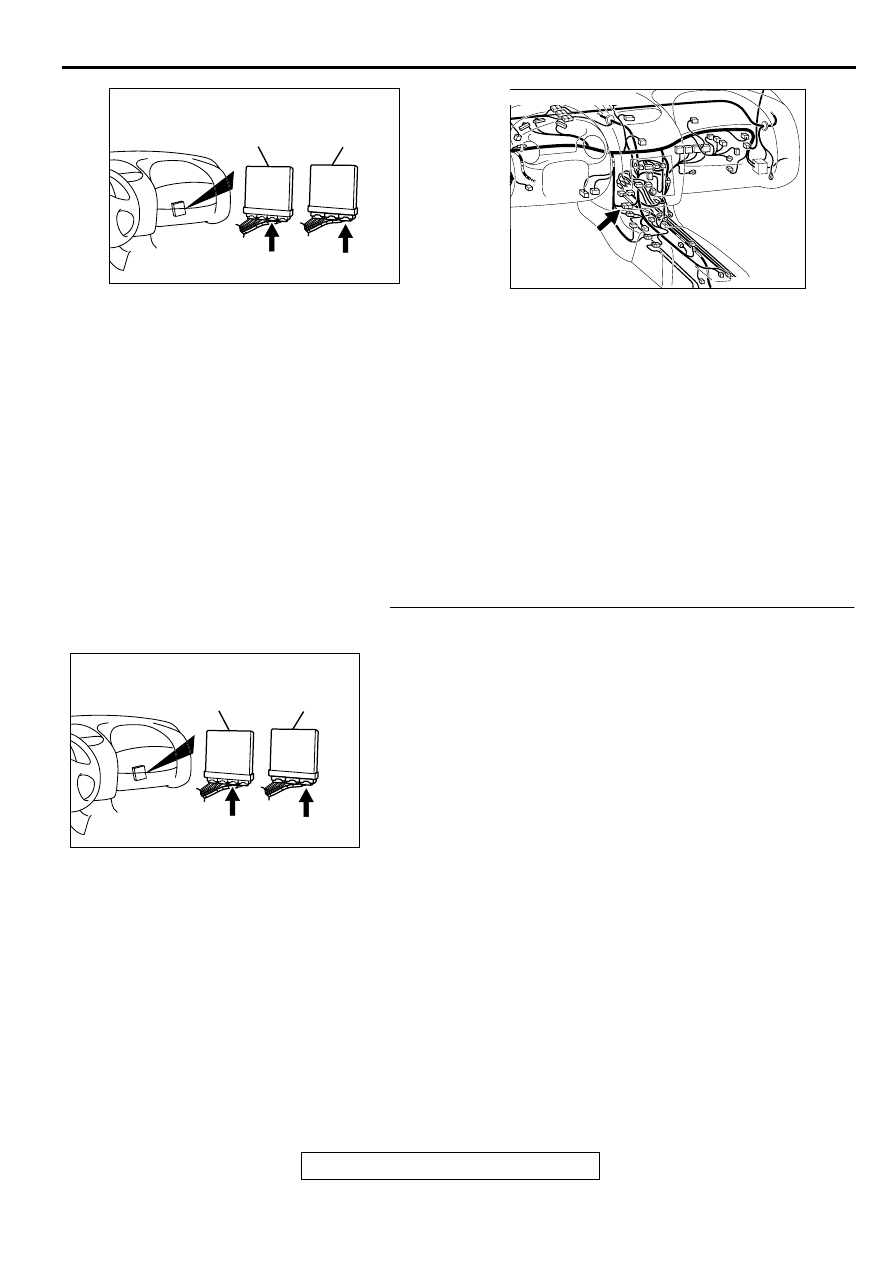
STEP 1. Check connector C-62 at ECM <M/T> or connector
C-59 at PCM <A/T> for damage.
Q: Is the connector in good condition?
YES : Go to Step 2.
NO : Repair or replace it. Refer to GROUP 00E, Harness
Connector Inspection (
). Then confirm that
the malfunction symptom is eliminated.
AK000225
CONNECTOR : C-62<M/T>, C-59<A/T>
C-59
C-62
PCM<A/T>
ECM<M/T>
AL
AK000733AC
CONNECTOR:C-28
AK000225
CONNECTOR : C-62<M/T>, C-59<A/T>
C-59
C-62
PCM<A/T>
ECM<M/T>
AL
Нет комментариевНе стесняйтесь поделиться с нами вашим ценным мнением.
Текст