Mitsubishi Eclipse / Eclipse Spyder (2000-2002). Service and repair manual — part 184
MULTIPORT FUEL INJECTION (MFI) DIAGNOSIS
TSB Revision
MULTIPORT FUEL INJECTION (MFI) <2.4L ENGINE>
13A-435
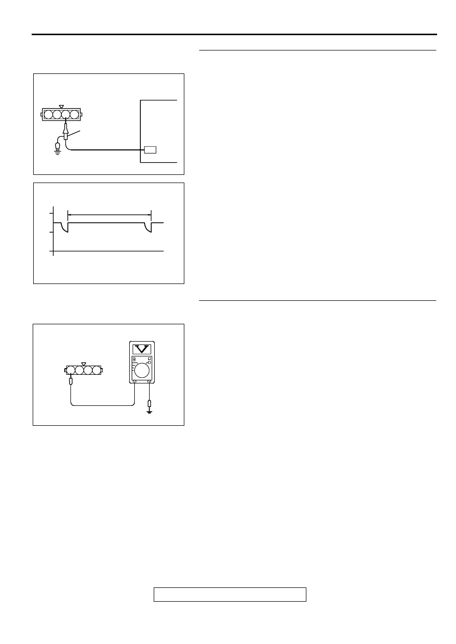
STEP 4. Using the oscilloscope, check the ignition failure
sensor.
(1) Disconnect the ignition failure sensor connector B-03, and
connect test harness special tool (MB991658) in between.
(All terminals should be connected.)
(2) Connect the oscilloscope probe to the ignition failure sensor
side connector terminal 3.
(3) Start the engine and run at idle.
(4) Check the waveform.
•
The waveform should show a pattern similar to the
illustration.
(5) Turn the ignition switch to the "LOCK" (OFF) position.
Q: Is the waveform normal?
YES : Go to Step 11.
NO : Go to Step 5.
STEP 5. Check the power supply voltage at ignition failure
sensor harness side connector B-03.
(1) Disconnect the connectors B-03 and measure at the
harness side.
(2) Turn the ignition switch to the "ON" position.
(3) Measure the voltage between terminal 4 and ground.
•
Voltage should be battery positive voltage.
(4) Turn the ignition switch to the "LOCK" (OFF) position.
Q: Is the voltage normal?
YES : Go to Step 6.
NO : Check connectors C-07, C-89 and C-101 at
intermediate connectors for damage, and repair or
replace as required. Refer to GROUP 00E, Harness
Connector Inspection (
). If intermediate
connectors are in good condition, repair harness wire
between ignition switch connector C-87 terminal 2
and ignition failure sensor connector B-03 terminal 4
because of open circuit. Then confirm that the
malfunction symptom is eliminated.
AK000411AB
OSCILLOSCOPE
PROBE
IGNITION FAILURE
SENSOR CONNECTOR
OSCILLOSCOPE
1 2 3 4
AK000412
NORMAL WAVEFORM (AT IDLING)
NOTE : CYCLE (T) SHORTENS AS
THE ENGINE SPEED RISES
(V)
15
14
13
AK000412AB
T
AK000413AB
B-03 HARNESS
SIDE CONNECTOR
1
2
3
4
MULTIPORT FUEL INJECTION (MFI) DIAGNOSIS
TSB Revision
MULTIPORT FUEL INJECTION (MFI) <2.4L ENGINE>
13A-436
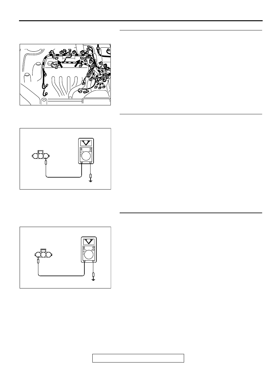
STEP 6. Check harness connector B-16, B-21 at ignition
coil for damage.
Q: Is the harness connector in good condition?
YES : Go to Step 7.
NO : Repair or replace it. Refer to GROUP 00E, Harness
Connector Inspection (
). Then confirm that
the malfunction symptom is eliminated.
STEP 7. Check the power supply voltage at ignition coil
connectors B-16, B-21.
(1) Disconnect the connector B-16, B-21 and measure at the
harness side.
(2) Turn the ignition switch to the "ON" position.
(3) Measure the voltage between terminal 1 and ground.
•
Voltage should be battery positive voltage.
(4) Turn the ignition switch to the "LOCK" (OFF) position.
Q: Is the voltage normal?
YES : Go to Step 8.
NO : Repair harness wire between ignition failure
connectors B-03 terminal 3 and ignition coil
connectors B-16, B-21 terminals 1 because of open
circuit. Then confirm that the malfunction symptom is
eliminated.
STEP 8. Check the circuit at ignition coil harness side
connector B-16, B-21.
(1) Disconnect the connectors B-16, B-21 and measure at the
harness side.
(2) Engine cranking.
(3) Measure the voltage between terminal 3 and ground.
•
Voltage should be 0.3 and 3.0 volts.
(4) Turn the ignition switch to the "LOCK" (OFF) position.
Q: Is the voltage normal?
YES : Repair harness wire or harness damage between
ignition coil connector B-16, B-21 terminal 2 and
ground because of open circuit or harness damage.
Then confirm that the malfunction symptom is
eliminated.
NO : Go to Step 9.
AK000362AB
AK000362
CONNECTORS : B-16, B-21
B-21 B-16
AK000414AB
B-16, B-21
HARNESS SIDE
CONNECTOR
1
2
3
AK000415 AB
B-16, B-21
HARNESS SIDE
CONNECTOR
1
2
3
MULTIPORT FUEL INJECTION (MFI) DIAGNOSIS
TSB Revision
MULTIPORT FUEL INJECTION (MFI) <2.4L ENGINE>
13A-437
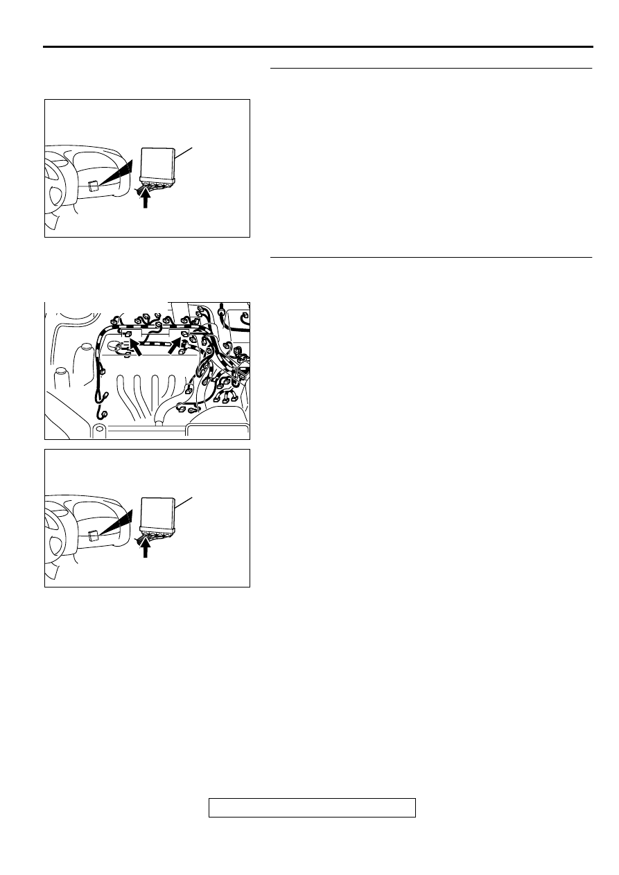
STEP 9. Check connector C-49 at ECM <M/T> or connector
C-50 at PCM <A/T> for damage.
Q: Is the connector in good condition?
YES : Go to Step 10.
NO : Repair or replace it. Refer to GROUP 00E, Harness
Connector Inspection (
). Then confirm that
the malfunction symptom is eliminated.
STEP 10. Check for open circuit between ignition coil
connector and ECM connector <M/T> or PCM connector
<A/T>.
a. Check the harness wire between ignition coil connector B-
16 terminal 3 and ECM connector C-49 terminal 10 <M/T>
or PCM connector C-50 terminal 11 <A/T> when checking
ignition coil 1.
b. Check the harness wire between ignition coil connector B-
21 terminal 3 and ECM connector C-49 terminal 23 <M/T>
or PCM connector C-50 terminal 12 <A/T> when checking
ignition coil 2.
Q: Is the harness wire in good condition?
YES : Replace the PCM. Then confirm that the malfunction
symptom is eliminated.
NO : Repair it. Then confirm that the malfunction symptom
is eliminated.
AK000280
C-49,C-50
ECM<M/T>
OR
PCM<A/T>
CONNECTORS:C-49<M/T>,C-50<A/T>
BC
AK000362AB
AK000362
CONNECTORS : B-16, B-21
B-21 B-16
AK000280
C-49,C-50
ECM<M/T>
OR
PCM<A/T>
CONNECTORS:C-49<M/T>,C-50<A/T>
BC
MULTIPORT FUEL INJECTION (MFI) DIAGNOSIS
TSB Revision
MULTIPORT FUEL INJECTION (MFI) <2.4L ENGINE>
13A-438
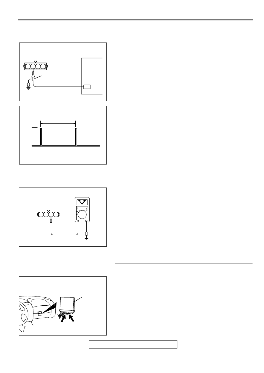
STEP 11. Using the oscilloscope, check the ignition failure
sensor.
(1) Disconnect the ignition failure sensor connector B-03, and
connect test harness special tool (MB991658) in between.
(All terminals should be connected.)
(2) Connect the oscilloscope probe to the ignition failure sensor
side connector terminal 2.
(3) Start the engine and run at idle.
(4) Check the waveform.
•
The waveform should show a pattern similar to the
illustration.
(5) Turn the ignition switch to the "LOCK" (OFF) position.
Q: Is the waveform normal?
YES : It can be assumed that this malfunction is intermittent.
Refer to GROUP 00, How to Use Troubleshooting/
Inspection Service Points (
NO : Go to Step 12.
STEP 12. Check the circuit at ignition failure sensor
harness side connector B-03.
(1) Disconnect the connectors B-03 and measure at the
harness side.
(2) Turn the ignition switch to the "ON" position.
(3) Measure the voltage between terminal 2 and ground.
•
Voltage should be 4 volts or more.
(4) Turn the ignition switch to the "LOCK" (OFF) position.
Q: Is the voltage normal?
YES : Repair harness wire between ignition failure sensor
connector B-03 terminal 1 and ground because of
open circuit or harness damage. Then confirm that
the malfunction symptom is eliminated.
NO : Go to Step 13.
STEP 13. Check connector C-56 at ECM <M/T> or
connector C-54 at PCM <A/T> for damage.
Q: Is the connector in good condition?
YES : Go to Step 9.
NO : Repair or replace it. Refer to GROUP 00E, Harness
Connector Inspection (
). Then confirm that
the malfunction symptom is eliminated.
AK000416 AB
OSCILLOSCOPE
PROBE
IGNITION FAILURE
SENSOR CONNECTOR
OSCILLOSCOPE
1 2 3 4
AK000417
NORMAL WAVEFORM (AT IDLING)
NOTE : CYCLE (T) SHORTENS AS
THE ENGINE SPEED RISES.
AK000417AB
10V
T
AK000418AB
B-03 HARNESS
SIDE CONNECTOR
1
2
3
4
AK000280
C-54
C-56
ECM<M/T>
OR
PCM<A/T>
CONNECTORS:C-56<M/T>,C-54<A/T>
BP
Нет комментариевНе стесняйтесь поделиться с нами вашим ценным мнением.
Текст