Mitsubishi Eclipse / Eclipse Spyder (2000-2002). Service and repair manual — part 182
MULTIPORT FUEL INJECTION (MFI) DIAGNOSIS
TSB Revision
MULTIPORT FUEL INJECTION (MFI) <2.4L ENGINE>
13A-427
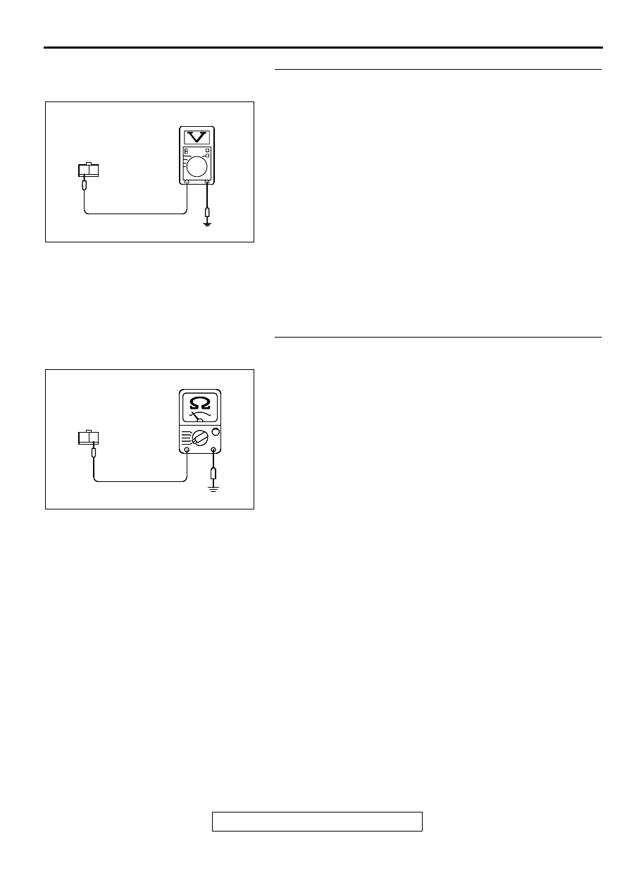
STEP 8. Check the power supply voltage at interlock
switch connector C-02.
(1) Disconnect the connector C-02 and measure at the harness
side.
(2) Turn the ignition switch to the "START" position.
(3) Measure the voltage between terminal 2 and ground.
•
Voltage should be battery positive voltage.
(4) Turn the ignition switch to the "LOCK" (OFF) position.
Q: Is the voltage normal?
YES : Go to Step 9.
NO : Check connector C-07 at intermediate connector for
damage, and repair or replace as required. Refer to
GROUP 00E, Harness Connector Inspection (
). If intermediate connectors is in good condition,
repair harness wire between starter relay connector
A-18X terminal 1 and interlock switch connector C-02
terminal 2 because of open circuit. Then confirm that
the malfunction symptom is eliminated.
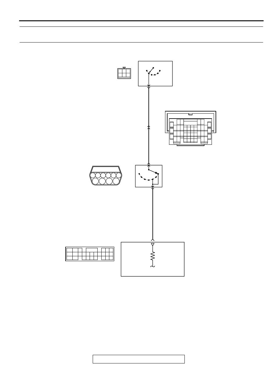
STEP 9. Check the continuity at interlock switch harness
side connector C-02.
(1) Disconnect the connector C-02 and measure at the harness
side.
(2) Check for the continuity between terminal 1 and ground.
•
Should be less than 2 ohm.
Q: Is the continuity normal?
YES : Replace the ECM. Then confirm that the malfunction
symptom is eliminated.
NO : Repair harness wire between interlock switch
connector C-02 terminal 1 and ground because of
open circuit or harness damage. Then confirm that
the malfunction symptom is eliminated.
AK000384AB
C-02 HARNESS
SIDE CONNECTOR
2 1
AK000385AB
C-02 HARNESS
SIDE CONNECTOR
2 1
MULTIPORT FUEL INJECTION (MFI) DIAGNOSIS
TSB Revision
MULTIPORT FUEL INJECTION (MFI) <2.4L ENGINE>
13A-428
INSPECTION PROCEDURE 32: Ignition Switch-ST System and Park/Neutral Position Switch System.
<A/T>
AK000682
7
10
5
3
1 2
4
6
9
4 5 6
1 2 3
8
BL
ACK
-RED
BL
ACK
-RED
BL
ACK
-RED
ACC
C-87
R
IGNITION
SWITCH
IG2
IG1
ST
LOCK
5
C-54
(MU803781)
POWERTRAIN CONTROL
MODULE(PCM)
58
PARK/
NEUTRAL
POSITION
SWITCH
B-41
MU802355
N
P
10
9
16
C-28
7 8
5
3 4
35
34
10 11 12
2122 23 24
13 14 15
25 26 27
16
28
17
18 19 20
29
30 31
32 33
36 37
38
9
1 2
6
42 43
48 49 50 51 52 53 54 55 56 57
46
45
44
58 59
60 61 62 63
64 65 66
47
41
MULTIPORT FUEL INJECTION (MFI) DIAGNOSIS
TSB Revision
MULTIPORT FUEL INJECTION (MFI) <2.4L ENGINE>
13A-429
COMMENT
•
If the selector lever is moved to "P" or "N" range
and the ignition switch is turned to "START"
position, battery positive voltage is supplied to
PCM (terminal 58) through the ignition switch and
park/neutral position switch. Because of this, the
PCM detects that the engine is cranking.
•
The park/neutral position switch detects the
selector lever position (P, N or other ranges) and
converts it to a voltage signal (high or low). Then
the park/neutral position switch sends that signal
to the PCM.
If the selector lever is moved to "P" or "N" range
with the ignition switch turned on (except
"START" position), continuity will exist between
the PCM and ground through the park/neutral
position switch and starter motor. The terminal
voltage of the PCM will become low. If the
selector lever is moved to the other ranges,
continuity will be lost between the PCM and
ground. The terminal voltage of the PCM will
become high.
TROUBLESHOOTING HINTS (The most likely
caused for this code to be set are:)
•
Malfunction of the ignition switch.
•
Malfunction of the park/neutral position switch.
•
Improper connector contact, open circuit or short-
circuit in the harness wire.
•
Malfunction of the PCM.
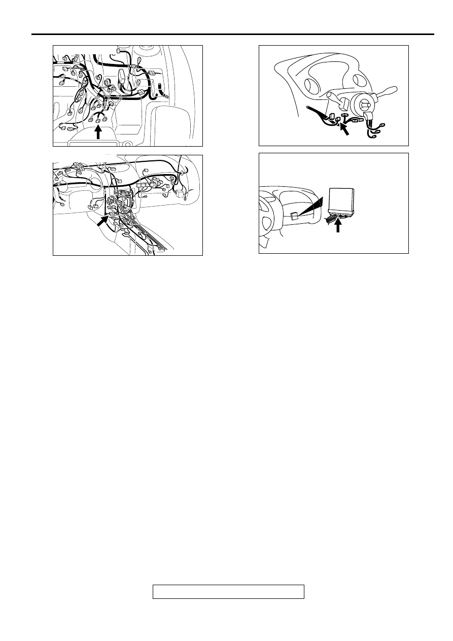
AK000547AE
CONNECTOR:B-41
AK000733AC
CONNECTOR:C-28
AK000219
CONNECTOR:C-87
AC
AK000280
CONNECTOR:C-54
BN
MULTIPORT FUEL INJECTION (MFI) DIAGNOSIS
TSB Revision
MULTIPORT FUEL INJECTION (MFI) <2.4L ENGINE>
13A-430
DIAGNOSIS
STEP 1. Check connector B-41 at park/neutral position
switch for damage.
Q: Is the connector in good condition?
YES : Go to Step 2.
NO : Repair or replace it. Refer to GROUP 00E, Harness
Connector Inspection (
). Then confirm that
the malfunction symptom is eliminated.
STEP 2. Check the park/neutral position switch.
Refer to GROUP 23A, On-vehicle Service
−
Essential Service
−
Park/Neutral Position Switch Continuity Check (
Q: Are there any abnormalities?
YES : Go to Step 3.
NO : Repair or replace it. Then confirm that the malfunction
symptom is eliminated.
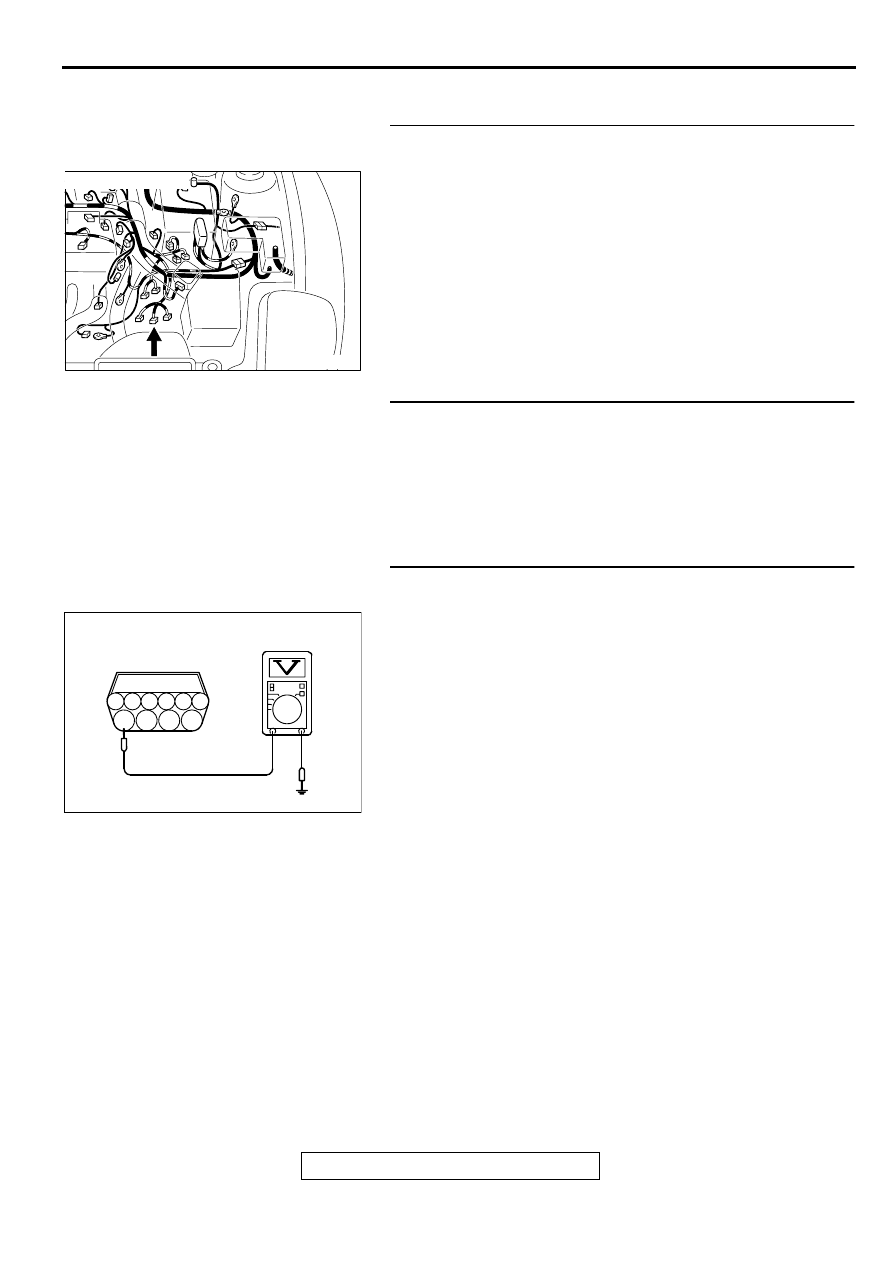
STEP 3. Check the power supply voltage at park/neutral
position switch connector B-41.
(1) Disconnect the connector B-41 and measure at the harness
side.
(2) Turn the ignition switch to the "START" position.
(3) Measure the voltage between terminal 10 and ground.
•
Voltage should be battery positive voltage.
(4) Turn the ignition switch to the "LOCK" (OFF) position.
Q: Is the voltage normal?
YES : Go to Step 4.
NO : Check connector C-28 at intermediate connector for
damage, and repair or replace as required. Refer to
GROUP 00E, Harness Connector Inspection (
). If intermediate connector is in good condition,
repair harness wire between ignition switch connector
C-87 terminal 5 and park/neutral position switch
connector B-41 terminal 10 because of open circuit.
Then confirm that the malfunction symptom is
eliminated.
AK000547AE
CONNECTOR:B-41
AK000386
B-41 HARNESS
SIDE CONNECTOR
6
1
2
3
4
5
7
8
9
10
AK000386AD
Нет комментариевНе стесняйтесь поделиться с нами вашим ценным мнением.
Текст