Mitsubishi Eclipse / Eclipse Spyder (2000-2002). Service and repair manual — part 185
MULTIPORT FUEL INJECTION (MFI) DIAGNOSIS
TSB Revision
MULTIPORT FUEL INJECTION (MFI) <2.4L ENGINE>
13A-439
STEP 14. Check for open circuit between ignition failure
sensor connector B-03 terminal 2 and ECM connector C-56
terminal 58 <M/T> or PCM connector C-54 terminal 43 <A/
T>.
Q: Is the harness wire in good condition?
YES : Replace the ECM or PCM. Then confirm that the
malfunction symptom is eliminated.
NO : Repair it. Then confirm that the malfunction symptom
is eliminated.
INSPECTION PROCEDURE 34: A/C system.
ACX02471
CONNECTOR : B-03
AF
IGNITION
FAILURE
SENSOR
AK000280
C-54
C-56
ECM<M/T>
OR
PCM<A/T>
CONNECTORS:C-56<M/T>,C-54<A/T>
BP
AK000684
GREEN-
RED
GREEN
ENGINE CONTROL
MODULE(ECM)<M/T>
OR
POWERTRAIN CONTROL
MODULE(PCM)<A/T>
45<M/T>*2
83<A/T>*4
8<M/T>*1
20<A/T>*3
C-49<M/T>
(MU803773)
C-53<M/T>
(MU803771)
C-50<A/T>
(MU803784)
C-57<A/T>
(MU803782)
A/C COMPRESSOR
RELAY
NOTE
*1:ECM connector C-49<M/T>
*2:ECM connector C-53<M/T>
*3:PCM connector C-50<A/T>
*4:PCM connector C-57<A/T>
AUTOMATIC
COMPRESSOR
CONTROLLER
6
17
8
15
9
18
7
20
16
2
10
13
12
23 24 25 26
11
21
3
1
14
4
19
5
22
12
11
16
5 6
7 8
21
13
27
14
28
15
29
17
30
18
31
19
32
20
33
22
34
23
35
1
24
3
26
9
2
25
10
4
34
33
32
36
35
37
42
45
31
39
38
46
40 41
43 44
98
78
71
88 89
76 77
72
79
91
73
80
74
75
81
92
8283
93
8485
94
8687
9596
90
97
MULTIPORT FUEL INJECTION (MFI) DIAGNOSIS
TSB Revision
MULTIPORT FUEL INJECTION (MFI) <2.4L ENGINE>
13A-440
COMMENT
•
When the A/C is "ON," the battery positive
voltage is applied on the ECM (terminal 45) <M/
T> PCM (terminal 83) <A/T> from the automatic
compressor controller.
When battery positive voltage is applied to the
ECM <M/T> or PCM <A/T>, the ECM <M/T> or
PCM <A/T> turns "ON" the power transistor in the
ECM <M/T> or PCM <A/T>. The ECM <M/T> or
PCM <A/T> delays A/C engagement momentarily
while it increases idle rpm. Then the A/C
compressor clutch relay coil will be energized.
With this, the A/C compressor clutch relay turns
"ON," and the A/C compressor clutch functions.
TROUBLESHOOTING HINTS (The most likely
causes for this case:)
•
Malfunction of the A/C control system.
•
Malfunction of the A/C switch.
•
Improper connector contact, open circuit or short-
circuited harness wire.
•
Malfunction of the ECM <M/T> or PCM <A/T>.
DIAGNOSIS
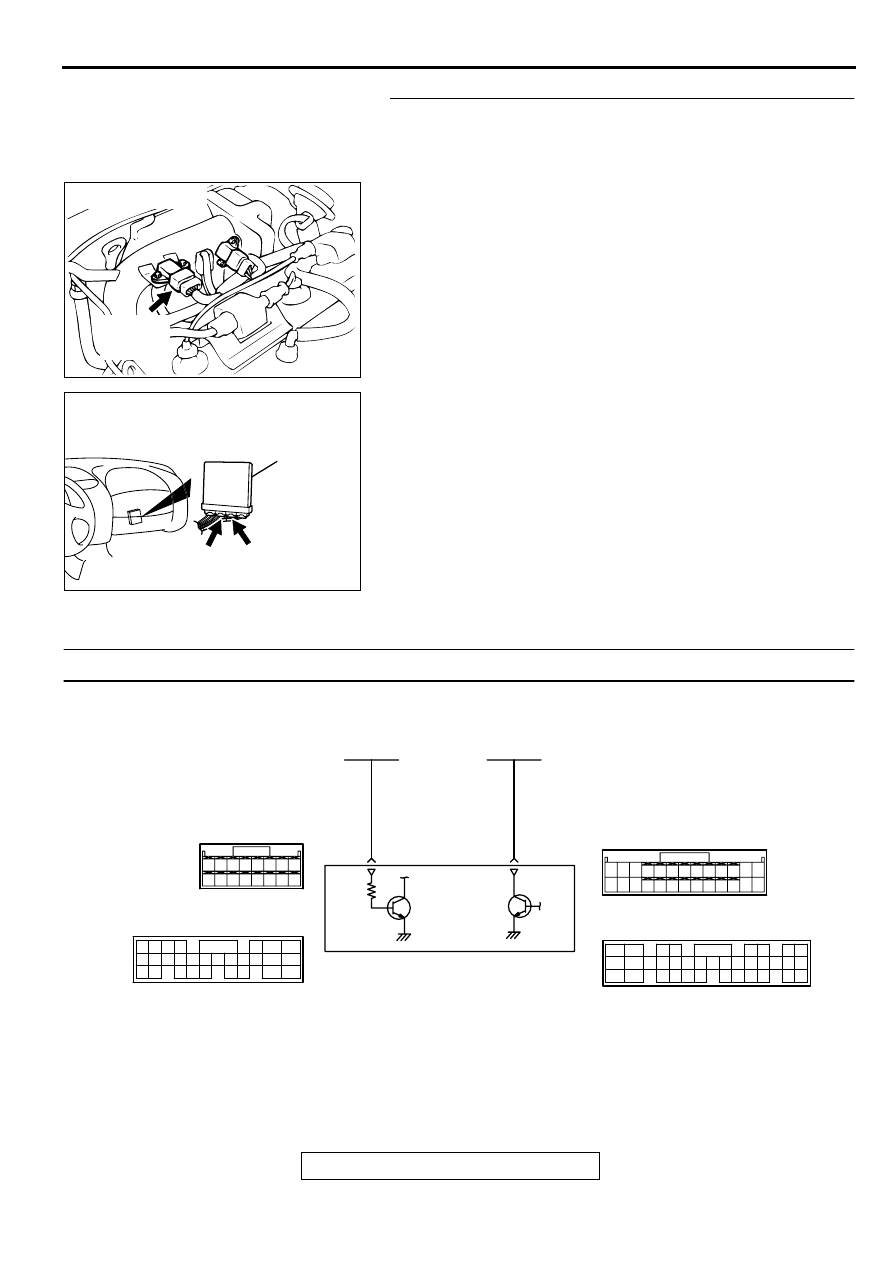
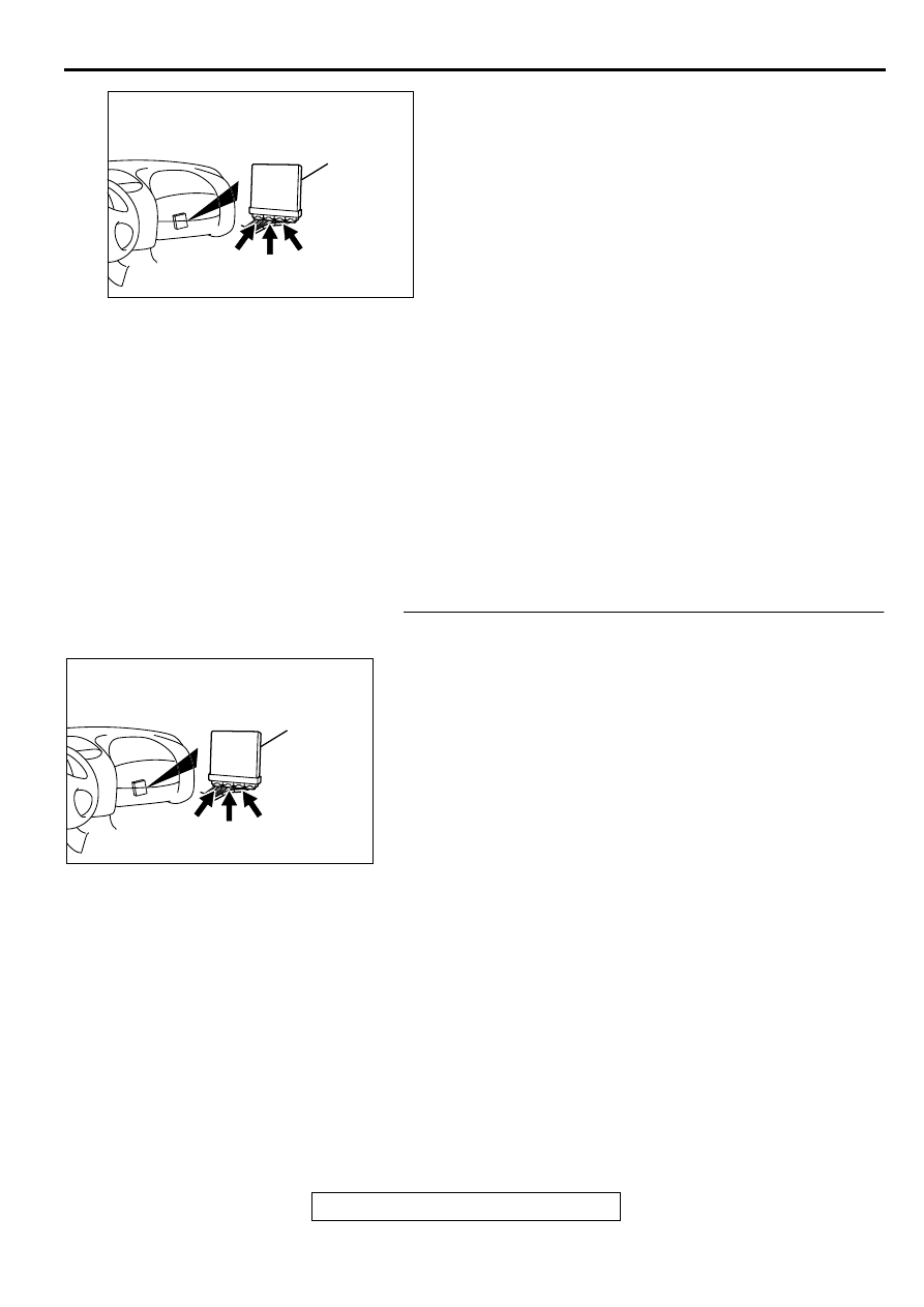
STEP 1. Check connector C-49, C-53 at ECM <M/T> or
connector C-50, C-57 at PCM <A/T> for damage.
Q: Is the connector in good condition?
YES : Go to Step 2.
NO : Repair or replace it. Refer to GROUP 00E, Harness
Connector Inspection (
). Then confirm that
the malfunction symptom is eliminated.
AK000280
C-49,
C-50
C-53
C-57
ECM<M/T>
OR
PCM<A/T>
CONNECTORS:C-49,C-53<M/T>,
C-50,C-57<A/T>
BQ
AK000280
C-49,
C-50
C-53
C-57
ECM<M/T>
OR
PCM<A/T>
CONNECTORS:C-49,C-53<M/T>,
C-50,C-57<A/T>
BQ
MULTIPORT FUEL INJECTION (MFI) DIAGNOSIS
TSB Revision
MULTIPORT FUEL INJECTION (MFI) <2.4L ENGINE>
13A-441
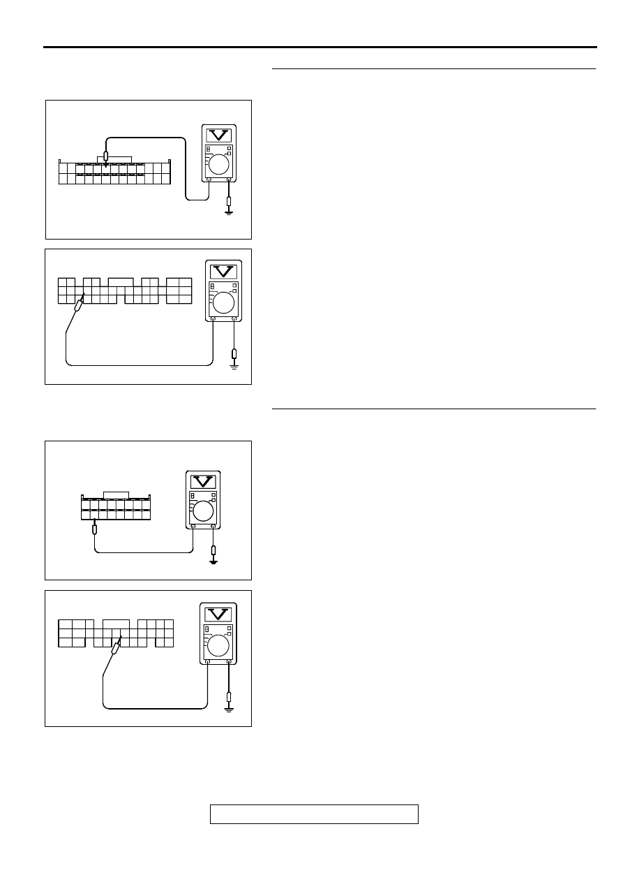
STEP 2. Check the circuit at ECM connector C-49 <M/T> or
PCM connector C-50 <A/T>.
(1) Disconnect the connectors C-49 <M/T> or C-50 <A/T> and
measure at the harness side.
(2) Turn the ignition switch to the "ON" position.
(3) Measure the voltage between terminal 8 <M/T> or 20 <A/T>
and ground.
•
Voltage should be battery positive voltage.
(4) Using a jumper wire, connect terminal 8 <M/T> or 20 <A/T>
to ground.
•
A/C compressor relay should turn "ON".
(5) Turn the ignition switch to the "LOCK" (OFF) position.
Q: Is the voltage and A/C compressor relay condition
normal?
YES : Go to Step 3.
NO : Refer to GROUP 55, Heating and air conditioning
−
Introduction To Heater, Air Conditioning And
Ventilation Diagnosis (
). Then confirm that the
malfunction symptom is eliminated.
STEP 3. Check the circuit at ECM connector C-53 <M/T> or
PCM connector C-57.
(1) Disconnect the connectors C-53 <M/T> or C-57 <A/T> and
measure at the harness side.
(2) Turn the ignition switch to the "ON" position.
(3) Measure the voltage between terminal 45 <M/T> or 83 <A/
T> and ground.
•
Voltage should be 1 volt or less when the A/C switch is
"OFF".
•
Voltage should be battery positive voltage when the A/C
switch is "ON".
(4) Turn the ignition switch to the "LOCK" (OFF) position.
Q: Is the voltage normal?
YES : Replace the ECM or PCM. Then confirm that the
malfunction symptom is eliminated.
NO : Refer to GROUP 55, Heating and air conditioning
−
Introduction To Heater, Air Conditioning And
Ventilation Diagnosis (
AK000419AC
1
2
3
4
5
6
7
8
9
10
11
12
13
14
15
16
17
18
19
20
21
22
23
24
25
26
<M/T>
C-49 HARNESS
SIDE CONNECTOR
AKX01448
1
2
3
4
5
6
7
8
9
10
11
12
13
14
15
16
17
18
19
20
21
22
23
24
25
26
28
29
30
31
32
33
34
35
36
C-50 HARNESS
SIDE CONNECTOR
<A/T>
AG
AK000420
<M/T>
C-53 HARNESS
SIDE CONNECTOR
AC
31
32
33
34
35
36
37
38
39
40
41
42
43
44
45
46
AKX01449
C-57 HARNESS
SIDE CONNECTOR
<A/T>
77 76
89 88
98
75
87
97
86
96
85
95
84
82
83
94 93
81
92
80
74 73 72 71
79 78
91 90
AG

MULTIPORT FUEL INJECTION (MFI) DIAGNOSIS
TSB Revision
MULTIPORT FUEL INJECTION (MFI) <2.4L ENGINE>
13A-442
DATA LIST REFERENCE TABLE
M1131008900154
CAUTION
•
When shifting the select lever to D range, the brakes should be applied so that the vehicle does
not move forward.
•
Driving tests always need two persons: one driver and one observer.
NOTE:
*1
: If the idle speed is lower than the standard value on a very cold engine (approximately -20
°
C (-4
°
F) even when the IAC motor is fully opened, the air volume limiter built in the throttle body could be defective.
NOTE:
*2
: In a new vehicle [driven approximately 500 km (311 mile) or less], the step of the stepper motor is
sometimes 30 steps greater than the standard value.
NOTE:
*3
: The injector drive time represents the time when the cranking speed is at 250 r/min or below when
the power supply voltage is 11 volts.
NOTE:
*4
: In a new vehicle [driven approximately 500 km (311 mile) or less], the injector drive time is
sometimes 10% longer than the standard time.
NOTE:
*5
: In a new vehicle [driven approximately 500 km (311 mile) or less], the volume air flow sensor
output frequency is sometimes 10% higher than the standard frequency.
NOTE:
*6
: Applicable to General Scan Tool (GST).
MUT-II SCAN
TOOL
DISPLAY
ITEM
NO.
INSPECTION
ITEM
INSPECTION REQUIREMENT
NORMAL
CONDITION
INSPECTION
PROCEDURE
NO.
REFERENCE
PAGE
A/C
RELAY
4
9
A/C
compressor
clutch relay
Engine:
warming up,
idling
A/C switch:
"OFF"
OFF
(Compressor
clutch is not
operating)
Procedure
No.34
A/C switch:
"ON"
ON
(Compressor
clutch is
operating)
A/C
SWITCH
28
A/C switch
Engine: idle
(when A/C
switch is ON,
A/C
compressor
should be
operating)
A/C switch:
"OFF"
OFF
Procedure
No.34
A/C switch:
"ON"
ON
BARO
SENSOR
25
Barometric
pressure
sensor
Ignition switch:
"ON"
At altitude of 0
m (0 ft)
101 kPa
Code No.
P0107,
P0108
At altitude of
600 m
(1,969 ft)
95 kPa
At altitude of
1,200 m
(3,937 ft)
88 kPa
At altitude of
1,800 m
(5,906 ft)
81 kPa
BATT
VOLTAGE
16
power supply
voltage
Ignition switch: "ON"
Battery positive
voltage
Procedure
No.29
Нет комментариевНе стесняйтесь поделиться с нами вашим ценным мнением.
Текст