Mitsubishi Eclipse / Eclipse Spyder (2000-2002). Service and repair manual — part 183
MULTIPORT FUEL INJECTION (MFI) DIAGNOSIS
TSB Revision
MULTIPORT FUEL INJECTION (MFI) <2.4L ENGINE>
13A-431
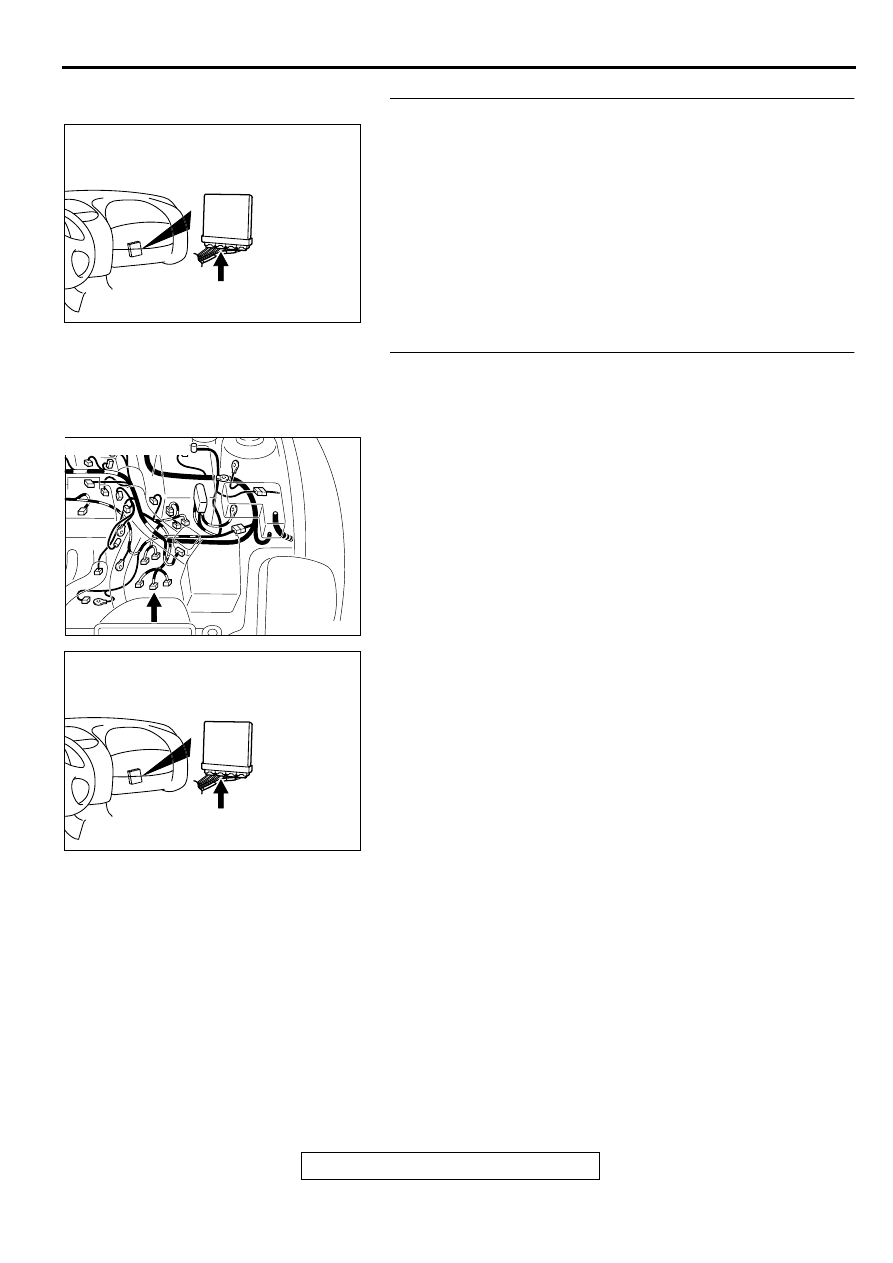
STEP 4. Check connector C-54 at PCM for damage.
Q: Is the connector in good condition?
YES : Go to Step 5.
NO : Repair or replace it. Refer to GROUP 00E, Harness
Connector Inspection (
). Then confirm that
the malfunction symptom is eliminated.
STEP 5. Check for open circuit and short circuit to ground
and harness damage between park/neutral position switch
connector B-41 terminal 9 and PCM connector C-54
terminal 58.
Q: Is the harness wire in good condition?
YES : Replace the PCM. Then confirm that the malfunction
symptom is eliminated.
NO : Repair it. Then confirm that the malfunction symptom
is eliminated.
AK000280
CONNECTOR:C-54
BN
AK000547AE
CONNECTOR:B-41
AK000280
CONNECTOR:C-54
BN
MULTIPORT FUEL INJECTION (MFI) DIAGNOSIS
TSB Revision
MULTIPORT FUEL INJECTION (MFI) <2.4L ENGINE>
13A-432
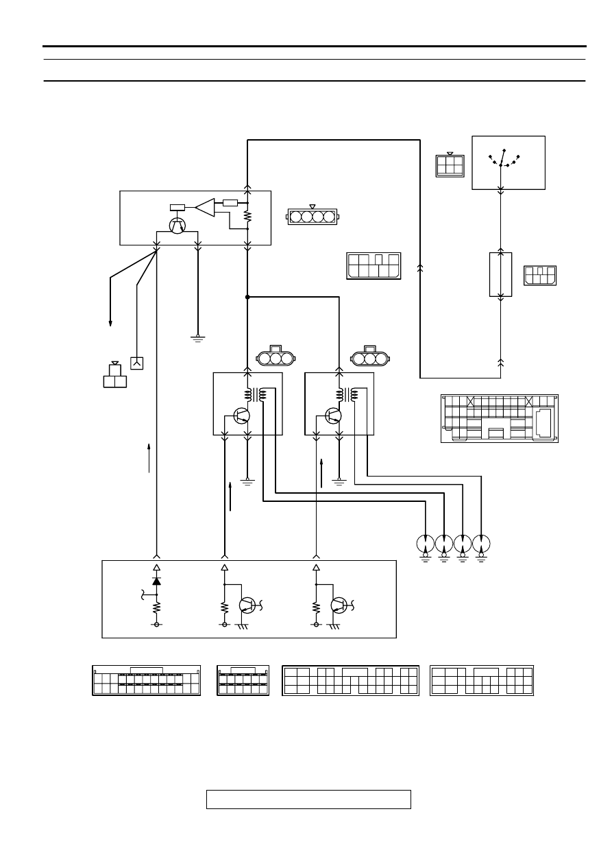
INSPECTION PROCEDURE 33 : Ignition Circuit System
AK000383
3
3
1
1
2
2
1 2
4
1 2 3
1
3
4 5 6
1
GREEN
3
2
4 5 6
7
2
6
3
5
1
4
BL
ACK
-
WHITE
3
8
2
WHITE-RED
WHITE-
RED
WHITE-
RED
BL
ACK
-BL
UE
BL
ACK
WHITE-
GREEN
BL
ACK
BL
ACK
BL
ACK
-
RED
BL
ACK
-
RED
BL
ACK
-
RED
BL
ACK
-WHITE
BL
ACK
-WHITE
TO
TACHOMETER
LOCK
ACC
IG1
IGNITION
SWITCH
C-87
2
6
5
29
C-89
R
C-101
MU801331
C-54<A/T>
(MU803781)
C-50<A/T>
(MU803784)
C-49<M/T>
(MU803773)
C-56<M/T>
(MU803770)
NOTE
*1:ECM connector C-49<M/T>
*2:ECM connector C-56<M/T>
*3:PCM connector C-50<A/T>
*4:PCM connector C-54<A/T>
58
<M/T>*2
43
<A/T>*4
10
<M/T>*1
11
<A/T>*3
23
<M/T>*1
12
<A/T>*3
IG2
ENGINE CONTROL
MODULE(ECM)<M/T>
OR
POWERTRAIN CONTROL
MODULE(PCM)<A/T>
ENGINE
SPEED
DETECTION
CONNECTOR
IGNITION
COIL 1
IGNITION
COIL 2
B-16
(MU802053)
A-16X
B-21
(MU802053)
3
C-07
MU801333
B-03
(MU802724)
JUNCTION
BLOCK
ST
2
2
1
1
3
3
1
2
3
3
4
SPARK PLUG
IGNITOIN FAILURE SENSOR
15 16
26 27 28 29
32 33 34
17 18 19 20 21 22 23 24 25
30 31
36 37
35
38
10
11 12 13
1 2 3
4 5 6 7 8 9
14
1
14
4
19
5
22
6
17
8
15
9
18
7
20
16
2
13
12
23 24 25 26
21
3
10 11
42 43
48 49 50 51 52 53 54 55 56 57
46
45
44
58 59
60 61 62 63
64 65 66
47
41
2
3 4
5 6
7 8
9
11 12 13 14 15 16 17 18 19 20
30
21 22 23
24 25
26 27 28 29
3132 33
34 35
1
10
58
60 61
53
52
51
55
54
56
59
62
57
MULTIPORT FUEL INJECTION (MFI) DIAGNOSIS
TSB Revision
MULTIPORT FUEL INJECTION (MFI) <2.4L ENGINE>
13A-433
CIRCUIT OPERATION
•
The ignition coil is energized by Battery positive
voltage from the ignition switch through the
ignition failure sensor.
•
When the ECM <M/T> or PCM <A/T> turns off its
internal power transistor, battery positive voltage
is applied to the ignition power transistor
(terminal 3) inside the ignition coil, causing the
ignition power transistor to be turned on.
•
If the ignition power transistor is turned on, the
primary circuit of the ignition coil is energized by
grounding the ignition coil through terminal 2,
causing the primary current to flow to the ignition
coil.
TROUBLESHOOTING HINTS (The most likely
causes for this case:)
•
Malfunction of the ignition coil.
•
Malfunction of the ignition power transistor.
ACX02471
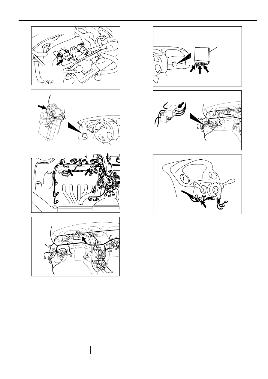
CONNECTOR : B-03
AF
IGNITION
FAILURE
SENSOR
AK000315
CONNECTOR:C-101
AC
AK000362AB
AK000362
CONNECTORS : B-16, B-21
B-21 B-16
AK000312AJ
CONNECTOR:C-07
AK000280
C-49,
C-50
C-54
C-60
ECM<M/T>
OR
PCM<A/T>
CONNECTORS:C-49,C-56<M/T>,
C-50,C-54<A/T>
BO
AK000345AE
CONNECTOR:C-89
AK000219
CONNECTOR:C-87
AC
MULTIPORT FUEL INJECTION (MFI) DIAGNOSIS
TSB Revision
MULTIPORT FUEL INJECTION (MFI) <2.4L ENGINE>
13A-434
•
Malfunction of the ignition failure sensor.
•
Improper connector contact, open circuit or short-
circuited harness wire.
•
Malfunction of the ECM <M/T> or PCM <A/T>.
DIAGNOSIS
STEP 1. Check the ignition failure sensor.
Refer to GROUP 16, Ignition System
−
On-vehicle sErvice
−
Ignition Failure Sensor Check (
Q: Are there any abnormalities?
YES : Go to Step 2.
NO : Replace the ignition failure sensor. Then confirm that
the malfunction symptom is eliminated.
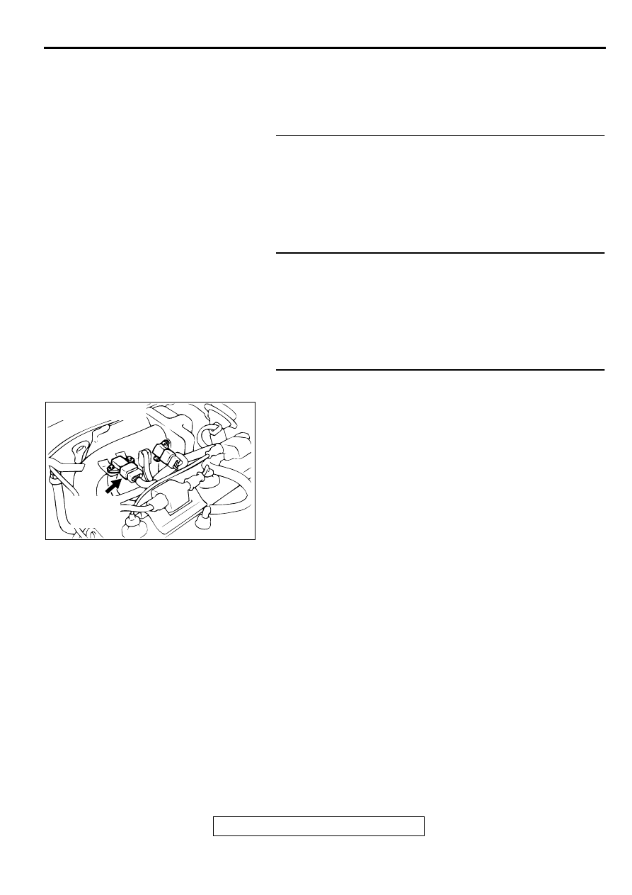
STEP 2. Check the ignition coil.
Refer to GROUP 16, Ignition System
−
On-vehicle sErvice
−
Ignition Coil Check (
).
Q: Are there any abnormalities?
YES : Go to Step 3.
NO : Replace the ignition coil. Then confirm that the
malfunction symptom is eliminated.
STEP 3. Check harness connectors B-03 at ignition failure
sensor for damage.
Q: Is the harness connector in good condition?
YES : Go to Step 4.
NO : Repair or replace it. Refer to GROUP 00E, Harness
Connector Inspection (
). Then confirm that
the malfunction symptom is eliminated.
ACX02471
CONNECTOR : B-03
AF
IGNITION
FAILURE
SENSOR
Нет комментариевНе стесняйтесь поделиться с нами вашим ценным мнением.
Текст