Mitsubishi Eclipse / Eclipse Spyder (2000-2002). Service and repair manual — part 269

MULTIPORT FUEL INJECTION (MFI) DIAGNOSIS
TSB Revision
MULTIPORT FUEL INJECTION (MFI) <3.0L ENGINE>
13B-275
STEP 1. Check the exhaust leaks.
Q: Are there any abnormalities?
YES : Go to Step 2.
NO : Repair it. Then go to Step 7.
STEP 2. Using scan tool MB991502, check data list item 69:
Heated Oxygen Sensor Bank 1, Sensor 2 (right rear).
CAUTION
To prevent damage to scan tool MB991502, always turn the
ignition switch to the "LOCK" (OFF) position before
connecting or disconnecting scan tool MB991502.
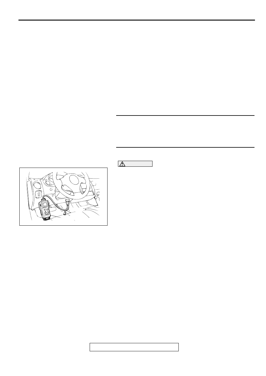
(1) Connect scan tool MB991502 to the data link connector.
(2) Start the engine and run at idle.
(3) Set scan tool MB991502 to the data reading mode for item
69, Heated Oxygen Sensor Bank 1, Sensor 2 (right rear).
•
Warming up the engine. When the engine is revved, the
output voltage should repeat 0 volt and 0.6 to 1.0 volt
alternately.
(4) Turn the ignition switch to the "LOCK" (OFF) position.
Q: Is the sensor operating properly?
YES : Go to Step 3.
NO : Refer to, DTC P0136
−
O
2
Sensor Circuit Malfunction
(bank 1 sensor 2) (
), DTC P0139
−
O
2
Sensor Circuit Slow Response (bank 1 sensor 2)
(
).
STEP 3. Using scan tool MB991502, check data list item 39:
Heated Oxygen Sensor Bank 1, Sensor 1 (right front).
(1) Start the engine and run at idle.
(2) Set scan tool MB991502 to the data reading mode for item
39, Heated Oxygen Sensor Bank 1, Sensor 1 (right front).
•
Warming up the engine. When the engine is revved, the
output voltage should be 0.6 to 1.0 volt.
(3) Turn the ignition switch to the "LOCK" (OFF) position.
Q: Is the sensor operating properly?
YES : Go to Step 4.
NO : Refer to, DTC P0130
−
O
2
Sensor Circuit Malfunction
(bank 1 sensor 1) (
), DTC P0133
−
O
2
Sensor Circuit Slow Response (bank 1 sensor 1)
(
).
AKX01177
16 PIN
MB991502
AB
AKX01177
16 PIN
MB991502
AB

MULTIPORT FUEL INJECTION (MFI) DIAGNOSIS
TSB Revision
MULTIPORT FUEL INJECTION (MFI) <3.0L ENGINE>
13B-276
STEP 4. Using scan tool MB991502, check data list item 39:
Heated Oxygen Sensor Bank 1, Sensor 1 (right front).
(1) Start the engine and run at idle.
(2) Set scan tool MB991502 to the data reading mode for item
39, Heated Oxygen Sensor Bank 1, Sensor 1 (right front).
(3) Keep the engine speed at 2,000 r/min.
•
0
−
0.4 and 0.6
−
1.0 volt should alternate 15 times or
more within 10 seconds.
(4) Turn the ignition switch to the "LOCK" (OFF) position.
Q: Is the sensor operating properly?
YES : Go to Step 5.
NO : Replace the right bank heated oxygen sensor (front).
Then go to Step 7.
STEP 5. Test the OBD-II drive cycle.
(1) Carry out a test drive with the drive cycle pattern. Refer to,
Procedure 3
−
Catalytic Converter Monitor (
(2) Check the diagnostic trouble code (DTC).
Q: Is the DTC P0421 is output?
YES : Replace the right bank side catalytic converter. Then
go to Step 6.
NO : The inspection is complete.
STEP 6. Test the OBD-II drive cycle.
(1) Carry out a test drive with the drive cycle pattern. Refer to,
Procedure 3
−
Catalytic Converter Monitor (
(2) Check the diagnostic trouble code (DTC).
Q: Is the DTC P0421 is output?
YES : Replace the ECM or PCM. Then go to Step 7.
NO : The inspection is complete.
STEP 7. Test the OBD-II drive cycle.
(1) Carry out a test drive with the drive cycle pattern. Refer to,
Procedure 3
−
Catalytic Converter Monitor (
(2) Check the diagnostic trouble code (DTC).
Q: Is the DTC P0421 is output?
YES : Retry the troubleshooting.
NO : The inspection is complete.
DTC P0431: Warm Up Catalyst Efficiency Below Threshold (bank 2)
TECHNICAL DESCRIPTION
•
The signal from the rear heated oxygen sensor
differs from the front heated oxygen sensor. That
is because the catalytic converter purifies
exhaust gas. When the catalytic converter has
deteriorated, the signal from the front heated
oxygen sensor becomes similar to the rear
heated oxygen sensor.
•
The ECM <M/T> or PCM <A/T> compares the
output of the front and rear heated oxygen sensor
signals.
DTC SET CONDITIONS
Check Conditions
•
Engine speed is lower than 3,000 r/min.
AKX01177
16 PIN
MB991502
AB
MULTIPORT FUEL INJECTION (MFI) DIAGNOSIS
TSB Revision
MULTIPORT FUEL INJECTION (MFI) <3.0L ENGINE>
13B-277
•
Volume air flow sensor output frequency is
between 69 and 169 Hz.
•
Intake air temperature is higher than -10
°
C (14
°
F).
•
Barometric pressure is higher than 76 kPa (11
psi).
•
The throttle valve is open.
•
Under the closed loop air / fuel ratio control.
•
Vehicle speed is 1.5 km/h (0.93 mph) or more.
•
Monitoring time: 84 seconds.
Judgment Criteria
•
The left bank heated oxygen sensor (rear) signal
and left bank heated oxygen sensor (front) signal
are similar.
TROUBLESHOOTING HINTS (The most likely
causes for this code to be set are:)
•
Left bank side catalytic converter deteriorated.
•
Left bank heated oxygen sensor failed.
•
ECM failed. <M/T>
•
PCM failed. <A/T>
DIAGNOSIS
Required Special Tools
MB991502: Scan Tool (MUT-II)
STEP 1. Check the exhaust leaks.
Q: Are there any abnormalities?
YES : Go to Step 2.
NO : Repair it. Then go to Step 7.
STEP 2. Using scan tool MB991502, check data list item 59:
Heated Oxygen Sensor Bank 2, Sensor 2 (left rear).
CAUTION
To prevent damage to scan tool MB991502, always turn the
ignition switch to the "LOCK" (OFF) position before
connecting or disconnecting scan tool MB991502.
(1) Connect scan tool MB991502 to the data link connector.
(2) Start the engine and run at idle.
(3) Set scan tool MB991502 to the data reading mode for item
59, Heated Oxygen Sensor Bank 2, Sensor 2 (left rear).
•
Warming up the engine. When the engine is revved, the
output voltage should repeat 0 volt and 0.6 to 1.0 volt
alternately.
(4) Turn the ignition switch to the "LOCK" (OFF) position.
Q: Is the sensor operating properly?
YES : Go to Step 3.
NO : Refer to, DTC P0156
−
O
2
Sensor Circuit Malfunction
(bank 2 sensor 2) (
), DTC P0159
−
O
2
Sensor Circuit Slow Response (bank 2 sensor 2)
(
).
AKX01177
16 PIN
MB991502
AB

MULTIPORT FUEL INJECTION (MFI) DIAGNOSIS
TSB Revision
MULTIPORT FUEL INJECTION (MFI) <3.0L ENGINE>
13B-278
STEP 3. Using scan tool MB991502, check data list item 11:
Heated Oxygen Sensor Bank 2, Sensor 1 (left front).
(1) Start the engine and run at idle.
(2) Set scan tool MB991502 to the data reading mode for item
11, Heated Oxygen Sensor Bank 2, Sensor 1 (left front).
•
Warming up the engine. When the engine is revved, the
output voltage should be 0.6 to 1.0 volt.
(3) Turn the ignition switch to the "LOCK" (OFF) position.
Q: Is the sensor operating properly?
YES : Go to Step 4.
NO : Refer to, DTC P0150
−
O
2
Sensor Circuit Malfunction
(bank 2 sensor 1) (
), DTC P0153
−
O
2
Sensor Circuit Slow Response (bank 2 sensor 1)
(
).
STEP 4. Using scan tool MB991502, check data list item 11:
Heated Oxygen Sensor Bank 2, Sensor 1 (left front).
(1) Start the engine and run at idle.
(2) Set scan tool MB991502 to the data reading mode for item
11, Heated Oxygen Sensor Bank 2, Sensor 1 (left front).
(3) Keep the engine speed at 2,000 r/min.
•
0
−
0.4 and 0.6
−
1.0 volt should alternate 15 times or
more within 10 seconds.
(4) Turn the ignition switch to the "LOCK" (OFF) position.
Q: Is the sensor operating properly?
YES : Go to Step 5.
NO : Replace the left bank heated oxygen sensor (front).
Then go to Step 7.
STEP 5. Test the OBD-II drive cycle.
(1) Carry out a test drive with the drive cycle pattern. Refer to,
Procedure 3
−
Catalytic Converter Monitor (
(2) Check the diagnostic trouble code (DTC).
Q: Is the DTC P0431 is output?
YES : Replace the left bank side catalytic converter. Then
go to Step 6.
NO : The inspection is complete.
STEP 6. Test the OBD-II drive cycle.
(1) Carry out a test drive with the drive cycle pattern. Refer to,
Procedure 3
−
Catalytic Converter Monitor (
(2) Check the diagnostic trouble code (DTC).
Q: Is the DTC P0431 is output?
YES : Replace the ECM or PCM. Then go to Step 7.
NO : The inspection is complete.
AKX01177
16 PIN
MB991502
AB
AKX01177
16 PIN
MB991502
AB
Нет комментариевНе стесняйтесь поделиться с нами вашим ценным мнением.
Текст