Acura RL (1996-2004 year). Manual — part 320

Alternator Replacement
1. Make sure you have the anti-theft code for the radio,
then write down the frequencies for the radio's pre-
set buttons.
2. Disconnect the battery negative terminal first, then
the positive terminal.
NOTE: The PCM memory must be reset after recon-
necting the battery (see page
).
3. Remove the battery and battery base (see page
).
4. Remove the mounting bolt, lock bolt and adjusting
rod, then remove the alternator belt.
LOCK BOLT
8 x 1.25 mm
22 N-m (2.2 kgf-m,
16 Ibf-ft)
ADJUSTING
ROD
ALTERNATOR
BELT
MOUNTING BOLT
10 x 1.25 mm
44 N-m (4.5 kgf-m,
33 Ibf-ft)
5. Remove the alternator bracket.
ALTERNATOR
BRACKET
10 x 1.25 mm
44 N-m (4.5 kgf-m,
33 Ibf-ft)
8 x 1.25 mm
22 N-m (2.2 kgf-m,
16 Ibf-ft)
6.
Disconnect the 4P connector and harness clip bracket,
then remove the terminal nut and the BLK wire from
the B terminal. Take out the alternator.
BLK WIRE
8 x 1.25 mm
12 N-m (1.2 kgf-m,
8.7 Ibf-ft)
4P CONNECTOR
ALTERNATOR
7. Install the reverse order of removal.
8. Adjust the alternator belt (see page
).
9. Enter the anti-theft code for the radio, then enter the
customer's radio station presets.
Main Menu
Table of Contents
Charging System
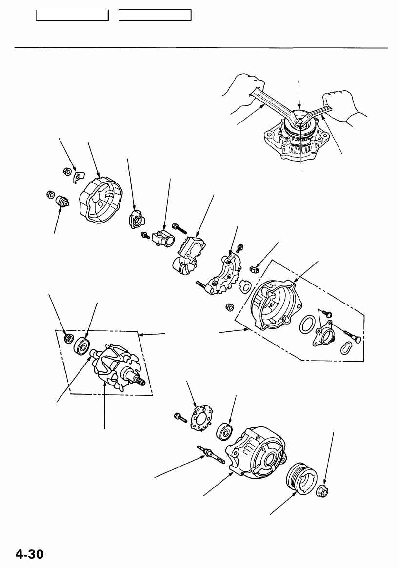
Alternator Overhaul
NOTE: Do not remove the pulley unless the front bear-
ing needs replacement.
To loosen the pulley locknut, use the tools as shown. If
necessary, use an impact wrench.
HARNESS
CLIP
BRACKET
PULLEY
END COVER
BRUSH HOLDER
INSULATOR
BRUSH ASSEMBLY
Inspection, page
22 mm BOX
WRENCH
10 mm BOX WRENCH
PULLEY LOCKNUT
110 N-m (11.3 kgf-m, 81.7 Ibf-ft)
VOLTAGE REGULATOR
TERMINAL INSULATOR
INSULATOR SLEEVE
REAR HOUSING
SPACER
CAUTION: Do not get grease
or oil on the slip rings.
ROTOR
Test, page
PULLEY LOCKNUT
110 N-m
(11.3 kgf-m, 81.7 Ibf-ft)
STATOR THROUGH BOLT
STATOR/DRIVE END HOUSING
Test, page
PULLEY
FRONT BEARING
BEARING RETAINER
Do not disassemble.
REAR BEARING
Main Menu
Table of Contents

Rectifier Test
NOTE: The diodes are designed to allow current to pass
in one direction while blocking it in the opposite direc-
tion. Since the alternator rectifier is made up of eight
diodes (four pairs), each diode must be tested for conti-
nuity in both directions with an ohmmeter that has diode
checking capability; a total of 16 checks.
1.
Check for continuity in each direction, between the
B and P, and between the E (ground) and P termi-
nals of each diode pair. All diodes should have con-
tinuity in only one direction.
2.
If any of the eight diodes fails, replace the rectifier
assembly. (Diodes are not available separately.)
Alternator Brush Inspection
1. Remove the end cover, then take out the brush holder
by removing its two screws.
2. Measure the length of the brushes with a vernier
caliper.
Alternator Brush Length:
Standard: 10.5 mm (0.41 in)
Service Limit: 1.5 mm (0.06 in)
ALTERNATOR BRUSHES
VERNIER CALIPER
If the brushes are less than the service limit, replace
the alternator brush assembly.
Main Menu
Table of Contents
Charging System
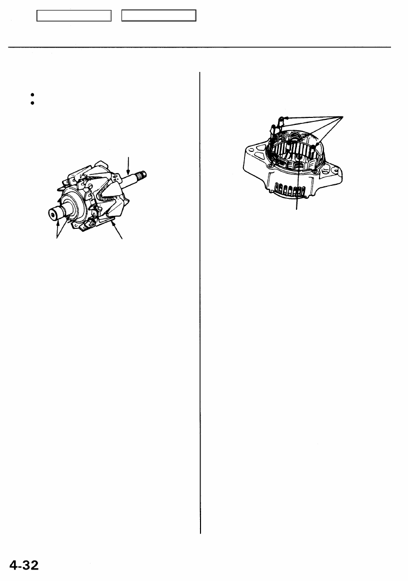
Rotor Slip Ring Test
1. Check the resistance between the slip rings.
There should be 2.9 ohms.
If resistance meets the specification, go to step 2.
If resistance does not meet the specification,
replace the alternator.
ROTOR SHAFT
SLIP RINGS
ROTOR
2. Check that there is no continuity between the slip
rings and the rotor or rotor shaft.
3. If the rotor fails either continuity check, replace the
alternator.
Stator Test
1. Check that there is continuity between each pair of
leads.
LEADS
COIL CORE
2. Check that there is no continuity between each lead
and the coil core.
3. If the coil fails either continuity check, replace the
alternator.
Main Menu
Table of Contents
Нет комментариевНе стесняйтесь поделиться с нами вашим ценным мнением.
Текст