Acura RL (1996-2004 year). Manual — part 319

Troubleshooting
If the charging system light does not come on or does not go off, or the battery is dead or low, test the following items in
the order listed below:
2. Charging System Light (see below)
3. Alternator/Regulator (see page
Charging System Light Test
Check the No. 20 (7.5 A) fuse in
the under-dash fuse/relay box.
Is the fuse OK?
Check for an open in the L circuit:
1. Disconnect the 4P connector
from the alternator.
2. Ground the No. 3 terminal of
the 4P connector.
3. Turn the ignition switch ON (II).
Does the charging system
light come on?
Disconnect the No. 3 terminal
of the 4P connector from the
ground.
Does the charging system
light go off?
Check for a short to body ground
in the L circuit:
1. Turn the ignition switch OFF.
2. Disconnect the ABS control
unit (C447) and passenger's
multiplex control unit (C401),
as applicable.
3. Turn the ignition switch ON (II).
Does the charging system
light stay off?
Check for short in control unit(s):
1. Turn the ignition switch OFF.
2. Reconnect the ABS control
unit connector.
3. Turn the ignition switch ON
(II), and check the charging
system light.
Did the light stay off when you
turned on the ignition switch
after connecting ABS control unit
connector?
Substitute a known-good ABS
control unit, and recheck.
ALTERNATOR
4P CONNECTOR
Replace the fuse.
Check for a blown charging sys-
tem light bulb. If the bulb is OK,
repair the open in the WHT/BLU
Wire side of
female terminals
(To page
Turn the ignition switch OFF, and
repair the short to ground in the
WHT/BLU wire.
Substitute a known-good pas-
senger's multiplex control unit,
and recheck.
Main Menu
Table of Contents

Charging System
Troubleshooting (cont'd)
(From page
Check for an open in the IG circuit:
Measure the voltage at the No. 1
terminal of the 4P connector.
Is there battery voltage?
Check the Alternator/Regulator:
1. Turn the ignition switch OFF.
2. Connect the 4P connector to
the alternator.
3. Turn the ignition switch ON
(II).
Does the charging system
light come on?
4. Start the engine.
Does the charging system
light go off?
The charging system light circuit
is OK.
Turn the ignition switch OFF, and
repair the open circuit in the BLK/
YEL wire.
ALTERNATOR
4P CONNECTOR
Wire side of
female terminals
Check the alternator/regulator
(see page
).
Check the alternator/regulator
(see page
).
Main Menu
Table of Contents
Alternator/Regulator Test
NOTE: Be sure the battery is sufficiently charged (see
).
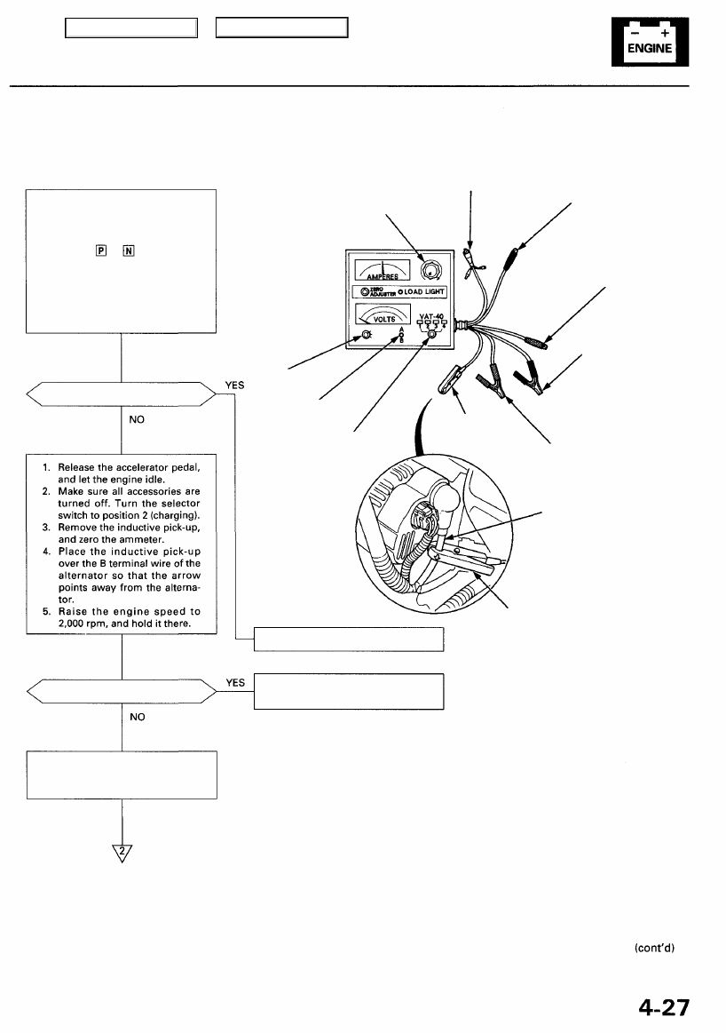
1. Connect the Sun VAT-40 (or
equivalent tester), and turn
the selector switch to position
1 (starting).
2. Shift to or position, and
start the engine. Hold the
engine at 3,000 rpm with no
load until the radiator fan
comes on, then let it idle.
3. Raise the engine speed to
2,000 rpm, and hold it there.
Is the voltage over 15.1 V?
Is the voltage less than 13.5 V?
Apply a load with the VAT-40
until the battery voltage drops to
between 12-13.5V.
FULL FIELD
TESTER
LEAD (BLU)
LOAD ADJUSTER
(CARBON PILE)
VOLTMETER
NEGATIVE
LEAD (BLK)
VOLT
SELECTOR
VOLTMETER
POSITIVE
LEAD (RED)
NEGATIVE TESTER
CABLE (BLK)
FIELD
SELECTOR
TEST SELECTOR
SWITCH
POSITIVE TESTER
CABLE (RED)
B TERMINAL
WIRE
INDUCTIVE
PICK-UP
Replace the voltage regulator.
Test and repair the alternator com-
ponents.
INDUCTIVE
PICK-UP
(GRN)
Main Menu
Table of Contents
Charging System
Troubleshooting (cont'd)
(From page
Is the amperage 75 A or more?
The charging system is OK.
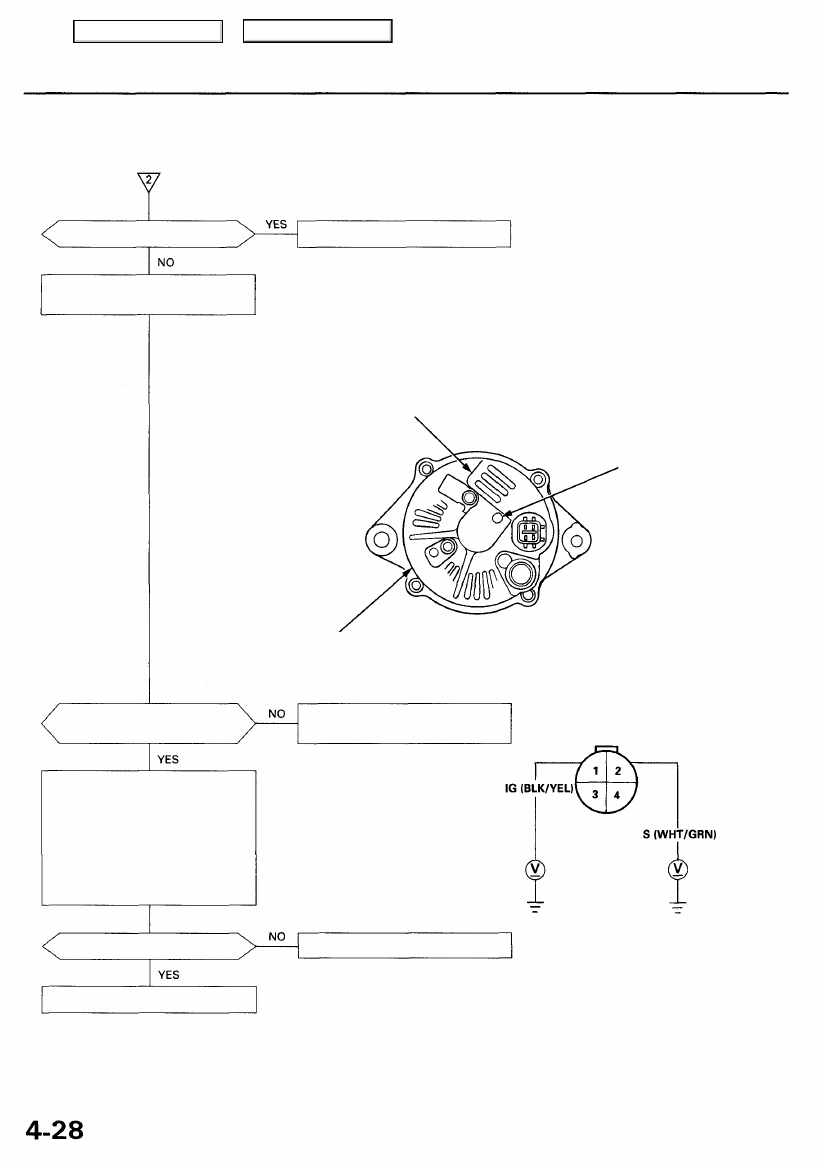
With the engine speed still at
2,000 rpm, full-field the alternator.
CAUTION: The voltage will rise quickly when the alternator is full-fielded. Do not allow
the voltage to exceed 18 V; it may damage the electrical system.
NOTE: Attach a probe to the VAT-40 full field test lead, and insert the probe into the full
field access hole at the back of the alternator. Switch the field selector to the "A (Ground)"
position momentarily, and check the amperage reading.
REGULATOR
(Located inside
the end cover)
FULL FIELD
ACCESS HOLE
END COVER
Is the alternator output 75 A or
more?
Test and repair the alternator com-
ponents.
ALTERNATOR
4P CONNECTOR
Test the BLK/YEL Wire:
1. Turn the ignition switch OFF,
then turn it on (II) again.
2. Disconnect the 4P connector
from the alternator.
3. Measure voltage between body
ground and alternator 4P con-
nector terminals No. 1 and
No. 2 individually.
Is there battery voltage?
Repair the open in the wire.
Wire side of
female terminals
Replace the voltage regulator.
Main Menu
Table of Contents
Нет комментариевНе стесняйтесь поделиться с нами вашим ценным мнением.
Текст