Acura RL (1996-2004 year). Manual — part 321
Alternator Belt Inspection and Adjustment
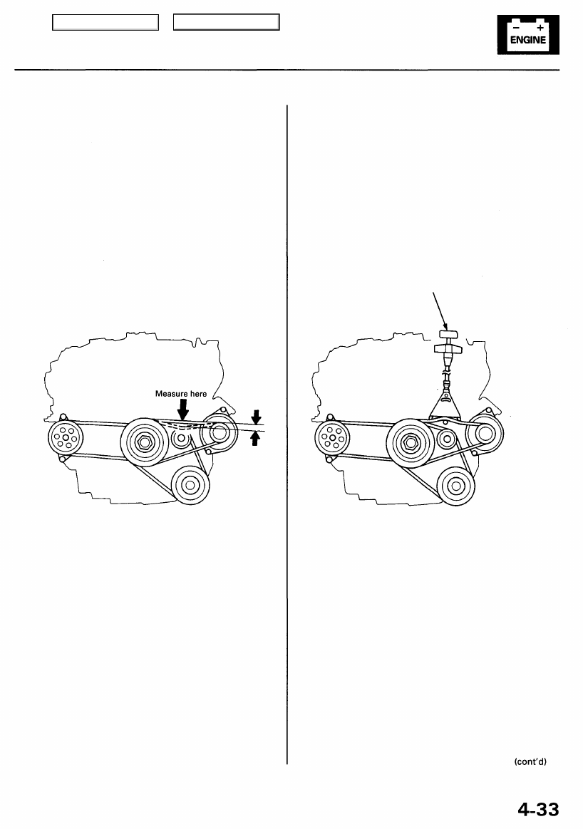
NOTE: When using a new belt, first adjust the deflection
or tension to the values for the new belt, then readjust
the deflection or tension to the values for the used belt
after running engine for 5 minutes.
Deflection method:
Apply a force of 98 N (10 kgf, 22 Ibf), and measure the
deflection between the alternator and crankshaft pulley.
Deflection:
Used Belt: 9.5 - 11.5 mm (0.37 - 0.45 in)
New Belt: 7.0 - 8.0 mm (0.28 - 0.31 in)
NOTE: If the belt is worn or damaged, replace it.
Belt tension gauge method:
Attach the belt tension gauge to the belt and measure the
tension. Follow the gauge manufacturer's instructions.
Tension:
Used Belt: 390 - 590 N (40 - 60 kgf, 88 - 130 Ibf)
New Belt: 780 - 980 N (80 - 100 kgf, 180 - 220 Ibf)
NOTE: If the belt is worn or damaged, replace it.
BELT TENSION GAUGE
Main Menu
Table of Contents
Charging System
Alternator Belt Inspection and
Adjustment (cont'd)
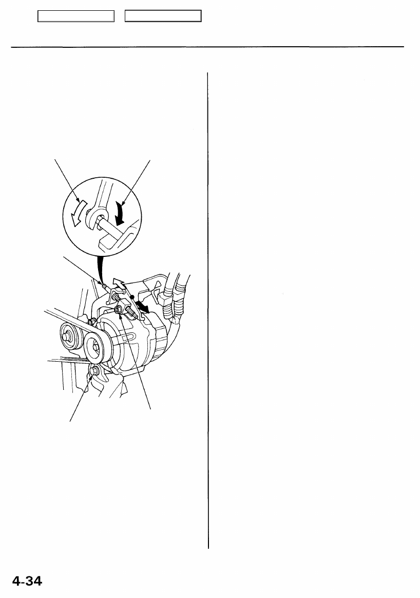
If adjustment is necessary:
1. Loosen the mounting bolt and the lock bolt.
2. Move the alternator by turning the adjusting rod to
obtain the proper belt tension, then retighten the
bolts.
Looser
Tighter
ADJUSTING
ROD
MOUNTING BOLT
10 x 1.25 mm
44 N-m (4.5 kgf-m,
33 Ibf-ft)
LOCK BOLT
8 x 1.25 mm
22 N-m (2.2 kgf-m,
16 Ibf-ft)
3. Recheck the deflection or tension of the belt.
NOTE: For the power steering pump belt and A/C
compressor belt adjustments, refer to
and
Main Menu
Table of Contents
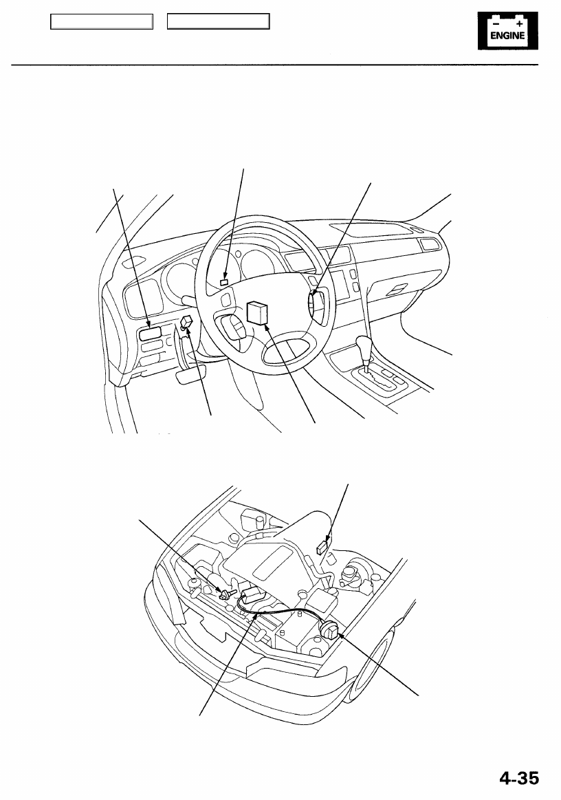
Cruise Control
Component Location Index
SRS components are located in this area. Review the SRS component locations, precautions, and procedures in the SRS
) before performing repairs or service.
CRUISE CONTROL INDICATOR LIGHT
MAIN SWITCH
Test/Replacement, page
SET/RESUME/CANCEL SWITCH
Test/Replacement, page
CRUISE CONTROL UNIT
Input Test, page
VEHICLE SPEED SENSOR (VSS)
Troubleshooting, page
TRANSMISSION RANGE
SWITCH
Test,
ACTUATOR CABLE
Adjustment, page
BRAKE PEDAL POSITION SWITCH
Test, page
Main Menu
Table of Contents
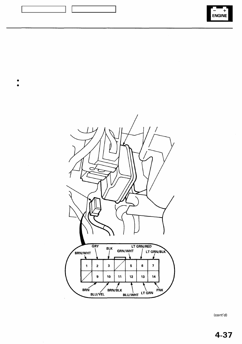
Control Unit Input Test
SRS components are located in this area. Review the SRS component locations, precautions, and procedures in the SRS
(
) before performing repairs or service.
1. Disconnect the 14P connector from the control unit.
2. Inspect the connector and socket terminals to be sure they are all making good contact.
If the terminals are bent, loose, or corroded, repair them as necessary, and recheck the system.
If the terminals look OK, make the following input tests at the connector.
— If any test indicates a problem, find and correct the cause, then recheck the system.
— If all the input tests prove OK, the control unit must be faulty; replace it.
CRUISE CONTROL UNIT
14P CONNECTOR
Wire side of female terminals
Main Menu
Table of Contents
Нет комментариевНе стесняйтесь поделиться с нами вашим ценным мнением.
Текст