Acura RL (1996-2004 year). Manual — part 333
NOTE:
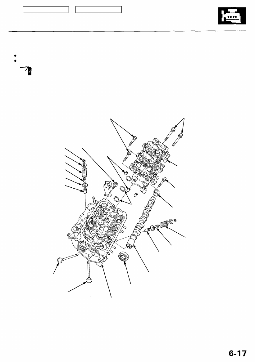
Use new O-rings and gaskets when reassembling.
Use liquid gasket, Part No. 08718 - 0001 or 08718 - 0003.
Prior to reassembling, clean all the parts in solvent, dry them, and apply lubricant to any contact parts.
6 x 1.0 mm
12 N-m (1.2 kgf-m, 8.7 Ibf-ft)
VALVE KEEPERS
SPRING RETAINER
INTAKE VALVE SPRING
VALVE SEAL
SPRING SEAT
VALVE GUIDE
EXHAUST VALVE
8 x 1.25 mm
22 N-m (2.2 kgf-m,
16 Ibf-ft)
6 x 1.0 mm
12 N-m (1.2 kgf-m,
8.7 Ibf-ft)
RUBBER PLUG
Apply liquid gasket.
VALVE GUIDE
Inspection, page
CAMSHAFT
Installation, page
OIL SEAL
Replace.
CYLINDER HEAD
Removal, page
Valve seat reconditioning,
EXHAUST VALVE SPRING
VALVE SEAL
ROCKER ARM
ASSEMBLY
Disassembly/Reassembly, page
DOWEL PIN
10 x 1.25 mm
44 N-m (4.5 kgf-m,
33 Ibf-ft)
O-RINGS
Replace.
Main Menu
Table of Contents

Cylinder Heads
Removal
Make sure jacks and safety stands are
placed properly and hoist brackets are attached to the
correct positions on the engine.
CAUTION:
Use fender covers to avoid damaging painted sur-
faces.
Unplug the wiring connectors carefully while holding
the connector portion to avoid damage.
To avoid damaging the cylinder head, wait until the
engine coolant temperature drops below 100°F (38°C)
before loosening the retaining bolts.
NOTE:
Unspecified items are common.
Mark all wiring and hoses to avoid misconnection.
Also, be sure that they do not contact other wiring or
hoses or interfere with other parts.
Inspect the timing belt before removing the cylinder
head.
Turn the crankshaft pulley so that the No. 1 piston is
at top dead center (TDC).
Do the PCM Memory Setting after reconnecting the
battery (see
).
1. Remove the support struts from the hood. Fix the
hood in a vertical position, then reinstall the sup-
port struts by using 6 x 1.0 mm bolts (see page
).
2. Make sure you have the anti-theft code for the radio,
then write down the frequencies for the radio's pre-
set buttons.
3. Disconnect the battery negative terminal first, then
the positive terminal.
4. Drain the engine coolant (see page
).
5. Remove the strut brace (see page
).
6. Remove the engine cover (see page
).
7. Remove the intake air duct and air cleaner housing
).
8. Remove the throttle cover (see page
).
9. Remove the throttle cable and cruise control cable
by loosening the locknuts, then slip the cable ends
out of the accelerator linkage (see page
).
NOTE:
Take care not to bend the cable when removing
it. Always replace any kinked cable with a new
one.
Adjust the throttle cable when installing (see
).
Adjust the cruise control cable when installing
).
10. Remove the upper radiator hose and water bypass
hose.
WATER BYPASS
HOSE
UPPER RADIATOR
HOSE
11. Raise the coolant reservoir, then remove the battery
and battery base.
BATTERY
BASE
6 x 1.0 mm
12 N-m (1.2 kgf-m,
8.7 Ibf-ft)
Main Menu
Table of Contents
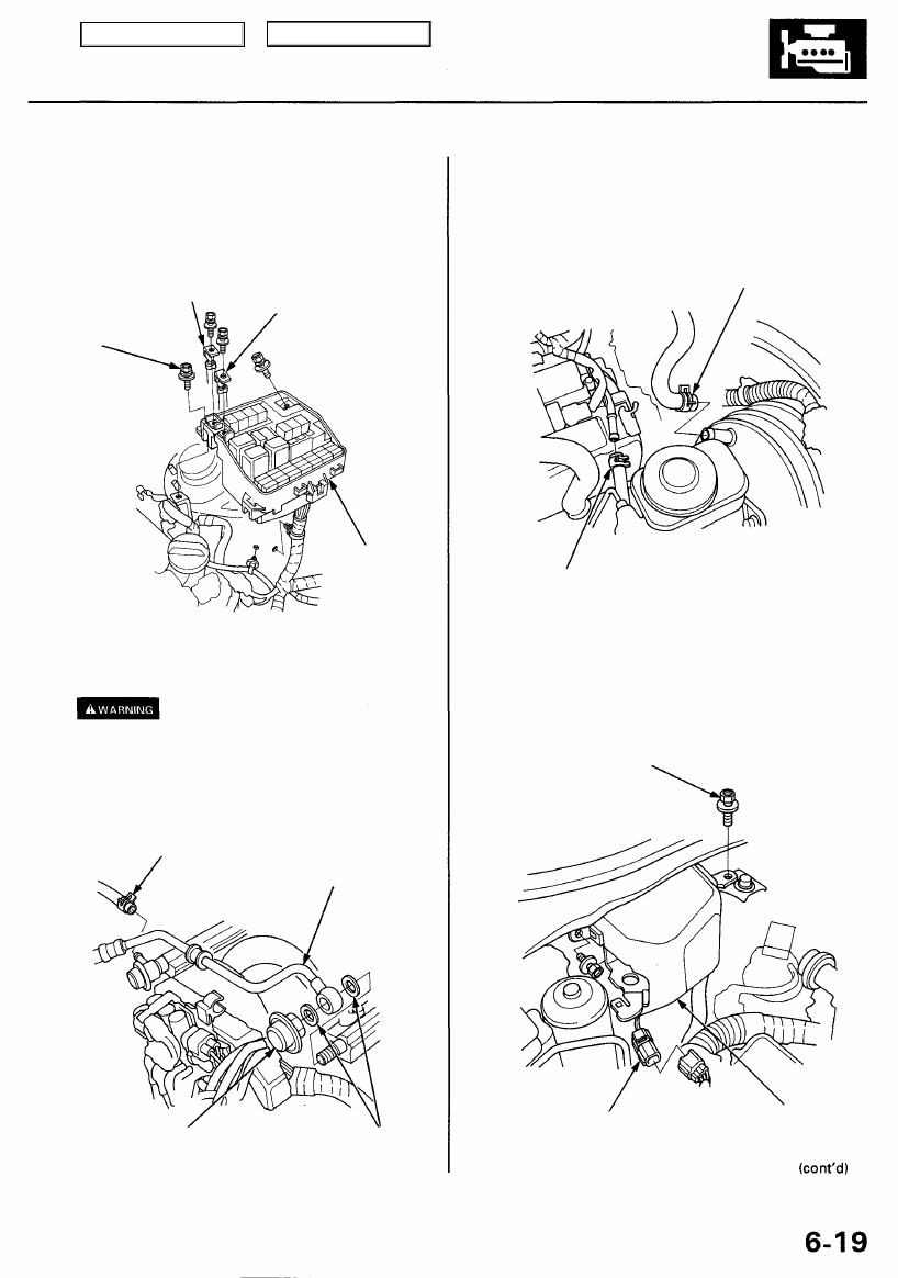
12. Remove the vacuum hoses, then remove the clamp
from the under-hood fuse/relay box (see page
).
13. Remove the battery cables from the under-hood
fuse/relay box, then remove the under-hood fuse/
relay box.
UNDER-HOOD
FUSE/RELAY
BOX
14. Relieve fuel pressure by loosening the service bolt
on the fuel filter about one turn (see
).
Do not smoke while working on the
fuel system. Keep open flame and sparks away from
the work area. Drain fuel only into an approved
container.
15. Remove the fuel feed hose and fuel return hose.
FUEL RETURN
HOSE
FUEL FEED
HOSE
FUEL PULSATION
DAMPER
22 N-m (2.2 kgf-m, 16 Ibf-ft)
WASHERS
Replace.
16. Remove the evaporative emission (EVAP) canister
hose and brake booster vacuum hose.
BRAKE BOOSTER
VACUUM HOSE
EVAP CONTROL
CANISTER HOSE
17. Disconnect the connector, then remove the control
box.
6 x 1.0 mm
12 N-m (1.2 kgf-m,
8.7 Ibf-ft)
CONNECTOR
CONTROL
BOX
BATTERY
CABLE
BATTERY
CABLE
6 x 1.0 mm
12 N-m (1.2 kgf-m,
8.7 Ibf-ft)
Main Menu
Table of Contents

Cylinder Heads
Removal (cont'd)
18. Loosen the mounting bolt, lock bolt and adjusting
rod, then remove the alternator belt.
ADJUSTING
ROD
LOCK BOLT
8 x 1.25 mm
22 N-m (2.2 kgf-m,
16 Ibf-ft)
ALTERNATOR
BELT
MOUNTING BOLT
10 x 1.25 mm
44 N-m (4.5 kgf-m,
33 Ibf-ft)
19. Loosen the idler pulley center nut and adjusting bolt,
then remove the air conditioning (A/C) compressor
belt.
ADJUSTING
BOLT
IDLER PULLEY
CENTER NUT
10 x 1.25 mm
44 N-m (4.5 kgf-m,
33 Ibf-ft)
A/C COMPRESSOR
BELT
20. Loosen the adjusting bolt, locknut and mounting bolt,
then remove the power steering (P/S) pump belt (see
).
21. Remove the vacuum hoses and breather hose.
22. Remove the vacuum hoses, then remove the igni-
tion control module (ICM) bracket (see page
).
23. Remove the engine wire harness connectors and
wire harness clamps from the cylinder heads and
intake manifold.
Six injector connectors
Six ignition coil connectors
Throttle position sensor connector
CKP/CYP sensor connector
Intake air temperature (IAT) sensor connector
Exhaust gas recirculation (EGR) valve connector
Idle air control (IAC) valve connector
Engine coolant temperature (ECT) sensor con-
nector
ECT gauge sending unit connector
Manifold absolute pressure (MAP) sensor con-
nector
Vehicle speed sensor (VSS) sub-connector
Left primary heated oxygen sensor (left primary
HO2S) connector
Right primary heated oxygen sensor (right pri-
mary H02S) connector
Ground cable (throttle body base)
VACUUM
HOSE
BREATHER
HOSE
Main Menu
Table of Contents
Нет комментариевНе стесняйтесь поделиться с нами вашим ценным мнением.
Текст