Acura RL (1996-2004 year). Manual — part 332
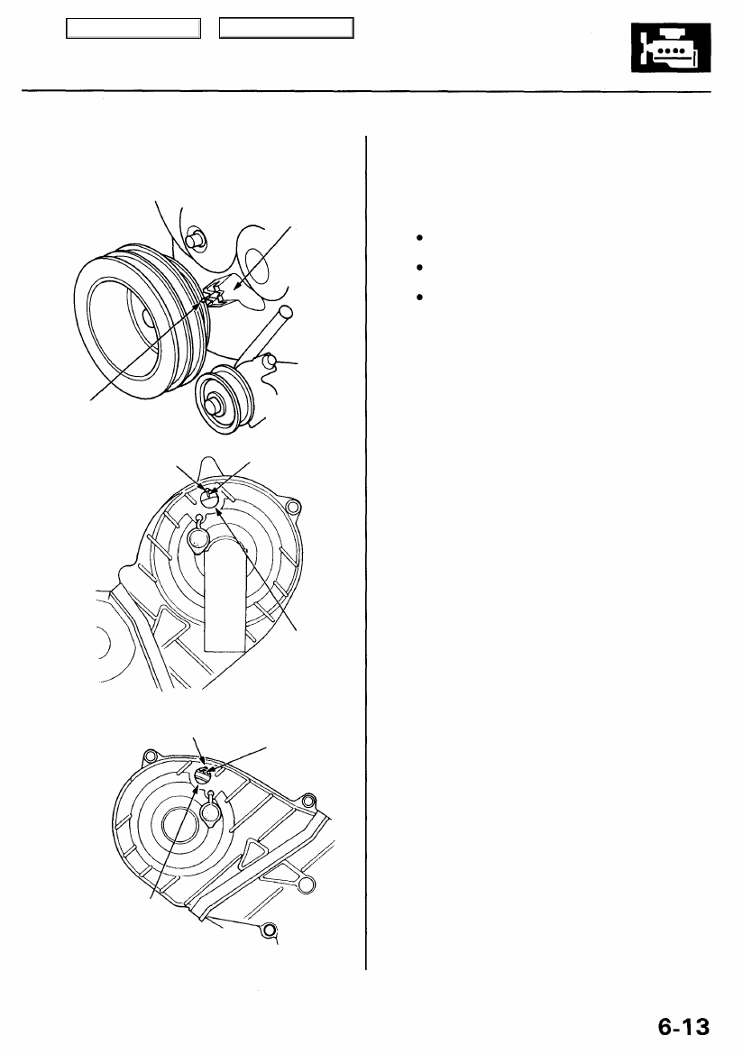
22. Check that the crankshaft pulley and camshaft pul-
leys are at TDC.
CRANKSHAFT PULLEY:
LOWER COVER
POINTER
TDC MARK
(BLUE)
RIGHT CAMSHAFT PULLEY:
UPPER COVER
POINTER
INSPECTION
HOLE
After checking,
install the rubber
cap.
TDC MARK
INSPECTION HOLE
After checking,
install the rubber
cap.
23. If the camshaft and crankshaft pulleys are not posi-
tioned at TDC, remove the timing belt and adjust the
positioning following the procedure on page
then reinstall the timing belt.
24. After installation, adjust the tension of each belt.
for alternator belt tension adjust-
for A/C compressor belt tension
for P/S pump belt tension adjust-
ment.
TDC MARK
(WHITE)
LEFT CAMSHAFT PULLEY:
UPPER COVER
POINTER
Main Menu
Table of Contents

CKP/CYP Sensor
Replacement
1. Turn the crankshaft so that the No. 1 piston is at top
dead center (see page
).
2. Remove the breather hose and vacuum hoses (see
).
3. Remove the vacuum hoses and ignition control
module (ICM) bracket (see page
).
4. Remove the upper covers.
5. Remove the timing belt from the right and left cam-
).
6. Remove the left camshaft pulley.
7. Remove the left back cover.
8. Remove the CKP/CYP sensor from the left cylinder
head.
9. Install the CKP/CYP sensor in the reverse order of
removal.
Refer to page
when installing the timing belt.
6 x 1.0 mm
12 N-m (1.2 kgf-m, 8.7 Ibf-ft)
RIGHT
UPPER COVER
LEFT
UPPER COVER
6 x 1.0 mm
12 N-m (1.2 kgf-m,
8.7 Ibf-ft)
LEFT CAMSHAFT
PULLEY
8 x 1.25 mm
31 N-m (3.2 kgf-m,
23 Ibf-ft)
6 x 1.0 mm
12 N-m (1.2 kgf-m,8.7 Ibf-ft)
RUBBER SEAL
Replace when damaged
or deteriorated.
LEFT BACK
COVER
RUBBER SEALS
Replace when damaged
or deteriorated.
CKP/CYP
SENSOR
Main Menu
Table of Contents
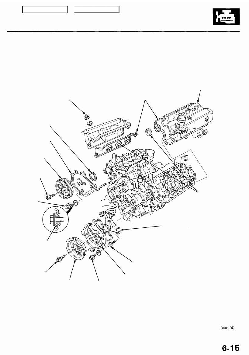
Cylinder Heads
Illustrated Index
NOTE: Use new O-rings and gaskets when reassembling.
6 x 1.0 mm
12 N-m (1.2 kgf-m, 8.7 Ibf-ft)
RUBBER SEAL
Replace when damaged
or deteriorated.
RIGHT BACK
COVER
6 x 1.0 mm
12 N-m (1.2 kgf-m,
8.7 Ibf-ft)
HEAD COVER GASKET
Replace when leaking, damaged
or deteriorated.
Apply liquid gasket at the four corners
of the recesses, page
CYLINDER HEAD COVER
when
installing.
8 x 1.25 mm
31 N-m (3.2 kgf-m, 23 Ibf-ft)
RUBBER SEALS
Replace when damaged
or deteriorated.
6 x 1.0 mm
12 N-m (1.2 kgf-m,
8.7 Ibf-ft)
LEFT BACK COVER
LEFT CAMSHAFT
PULLEY
6 x 1.0 mm
12 N-m (1.2 kgf-m,
8.7 Ibf-ft)
CKP/CYP
SENSOR
RIGHT CAMSHAFT
PULLEY
8 x 1.25 mm
31 N-m (3.2 kgf-m,
23 Ibf-ft)
GROMMET
Main Menu
Table of Contents
Cylinder Heads
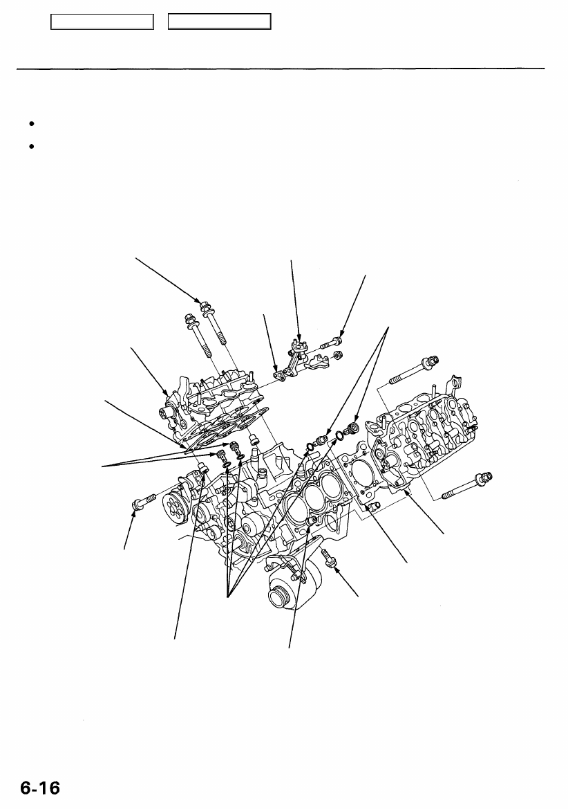
Illustrated Index (cont'd)
CAUTION:
To avoid damage, wait until the engine coolant temperature drops below 100°F (38°C) before removing a cylinder
head.
When handling a metal gasket, take care not to fold it or damage the contact surface.
NOTE: Clean the oil control orifice when installing.
CYLINDER HEAD BOLT
11 x 1.5 mm
76 N-m (7.8 kgf-m, 56 Ibf-ft)
Apply engine oil to the
bolt threads.
EXHAUST GAS
RECIRCULATION
(EGR) PASSAGE
8 x 1.25 mm
22 N-m (2.2 kgf-m,
16 Ibf-ft)
OIL CONTROL
ORIFICES
Remove with 6 x 1.0 mm
bolt and clean.
RIGHT CYLINDER
HEAD GASKET
Replace.
OIL CONTROL
ORIFICES
Remove with 6 x 1.0 mm
bolt and clean.
10 x 1.25 mm
44 N-m (4.5 kgf-m,
33 Ibf-ft)
LEFT CYLINDER
HEAD GASKET
Replace.
8 x 1.25 mm
22 N-m (2.2 kgf-m,
16 Ibf-ft)
DOWEL PIN
DOWEL PIN
GASKET
Replace.
CYLINDER
HEAD
O-RINGS
Replace.
CYLINDER
HEAD
Main Menu
Table of Contents
Нет комментариевНе стесняйтесь поделиться с нами вашим ценным мнением.
Текст