Acura RL (1996-2004 year). Manual — part 330
Balancer Belt
Inspection
1. Remove the engine cover (see page
).
2. Remove the intake air duct and air cleaner housing
).
3. Loosen the mounting bolt, lock bolt and adjusting
rod, then remove the alternator belt (see page
).
4. Loosen the idler pulley center nut and adjusting
bolt, then remove the air conditioning (A/C) com-
pressor belt (see page
).
5. Remove the TCS control valve upper and lower
).
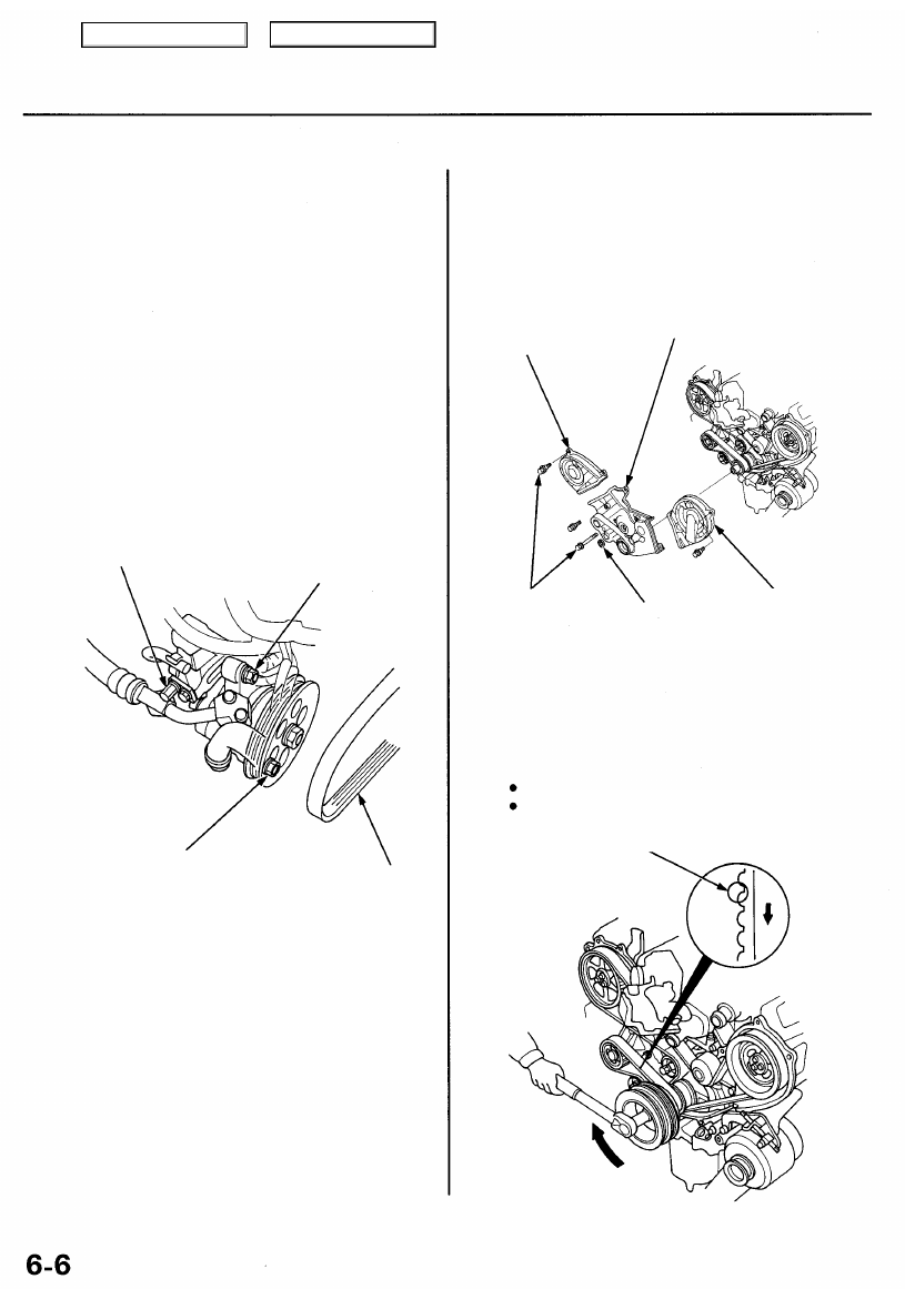
6. Loosen the adjusting bolt, locknut and mounting
bolt, then remove the power steering (P/S) pump
belt.
ADJUSTING
BOLT
LOCKNUT
8 x 1.25 mm
22 N-m (2.2 kgf-m,
16 Ibf-ft)
MOUNTING BOLT
10 x 1.25 mm
44 N-m (4.5 kgf-m,
33 Ibf-ft)
P/S PUMP
BELT
7. Disconnect the TCS throttle sensor connector and
TCS throttle actuator connector, then remove the
TCS control valve assembly (see page
).
8. Disconnect the vehicle speed sensor (VSS) sub-har-
ness connector, then remove the wire harness holder
(see page
).
9. Remove the breather hose and vacuum hoses (see
).
10. Remove the vacuum hoses and ignition control
module (ICM) bracket (see page
).
11. Remove the crankshaft pulley (see page
).
12. Remove the idler pulley, the dipstick, and the dip-
).
13. Remove the upper and lower covers.
RIGHT UPPER
COVER
LOWER
COVER
6 x 1.0 mm
12 N-m (1.2 kgf-m,
8.7 Ibf-ft)
RUBBER
SEAL
LEFT UPPER
COVER
14. Inspect the balancer belt for cracks and oil or
coolant soaking.
NOTE:
Replace the belt if oil or coolant soaked.
Remove any oil or solvent that gets on the belt.
Rotate pulley and
inspect the belt.
Inspect this area
for wear.
Main Menu
Table of Contents
Tension Adjustment
CAUTION:
Always adjust the balancer belt tension with the
engine cold.
Do not rotate the crankshaft when the adjusting bolt
is loose.
NOTE:
The tensioner is spring-loaded to apply tension to the
belt automatically after making the following adjust-
ment.
Inspect the balancer belt before adjusting the belt
tension.
Always rotate the crankshaft clockwise when viewed
from the pulley side. Rotating it counterclockwise may
result in improper adjustment of the belt tension.
1. Remove the engine cover (see page
).
2. Remove the intake air duct and air cleaner housing
).
3. Loosen the mounting bolt, lock bolt and adjusting
rod, then remove the alternator belt (see page
).
4. Loosen the idler pulley center nut and adjusting
bolt, then remove the air conditioning (A/C) com-
pressor belt (see page
).
5. Loosen the adjusting bolt, locknut and mounting
bolt, then remove the power steering (P/S) pump
belt (see page
).
6. Remove the TCS control valve upper and lower
).
7. Disconnect the TCS throttle sensor connector and
TCS throttle actuator connector, then remove the
TCS control valve assembly (see page
).
8. Disconnect the vehicle speed sensor (VSS) sub-har-
ness connector, then remove the wire harness holder
(see page
).
9. Remove the breather hose and vacuum hoses (see
).
10. Remove the vacuum hoses and ignition control
module (ICM) bracket (see page
).
11. Remove the crankshaft pulley (see page
).
12. Remove the upper and lower covers (see page
).
13. Set the No. 1 piston at TDC (see page
).
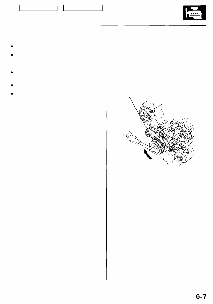
14. Rotate the crankshaft clockwise one turn.
15. Loosen the balancer belt adjusting bolt 180°.
16. Tighten the adjusting bolt, torque to 44 N - m
(4.5 kgf-m, 33 Ibf-ft).
BALANCER BELT
ADJUSTING BOLT
44 N-m (4.5 kgf-m,
33 Ibf-ft)
Direction
of rotation.
Main Menu
Table of Contents

Timing Belt and Balancer Belt
Removal
NOTE:
Replace the timing belt and timing balance belt at
105,000 miles (168,000 km) according to the mainte-
nance schedule (normal conditions, severe condi-
tions). If the vehicle regularly is driven in one or more
of the following conditions, replace the timing belt
and timing balancer belt at 60,000 miles (U.S.A.)
100,000 km (Canada).
— In very high temperatures (over 110°F, 43°C).
— In very low temperatures (under -20°F, -29°C).
Turn the crankshaft pulley so the No. 1 piston is at
top dead center (TDC) before removing the belt (see
page
).
Inspect the water pump before installing the timing
belt (see page
).
1. Remove the engine cover (see page
).
2. Remove the intake air duct and air cleaner housing
).
3. Loosen the mounting bolt, lock bolt and adjusting
rod, then remove the alternator belt (see page
).
4. Loosen the idler pulley center nut and adjusting
bolt, then remove the air conditioning (A/C) com-
pressor belt (see page
).
5. Remove the TCS control valve upper and lower
when installing the
brackets.
TCS CONTROL
VALVE LOWER
BRACKET
8 x 1.25 mm
22 N-m (2.2 kgf-m, 16 Ibf-ft)
6. Loosen the adjusting bolt, locknut and mounting
bolt, then remove the power steering (P/S) pump
belt (see page
).
7. Disconnect the TCS throttle sensor connector, the
TCS throttle actuator connector, and the throttle
position (TP) sensor connector, then remove the
TCS control valve assembly.
TCS THROTTLE
SENSOR CONNECTOR
TCS CONTROL
VALVE
ASSEMBLY
THROTTLE POSITION
(TP) SENSOR CONNECTOR
TCS THROTTLE
ACTUATOR
CONNECTOR
8. Disconnect the vehicle speed sensor (VSS) sub-har-
ness connector, then remove the wire harness holder.
WIRE HARNESS
HOLDER
VSS SUB-HARNESS
CONNECTOR
6 x 1.0 mm
12 N-m (1.2 kgf-m, 8.7 Ibf-ft)
6 x 1.0 mm
12 N-m (1.2 kgf-m,
8.7 Ibf-ft)
TCS CONTROL
VALVE UPPER
BRACKET
Main Menu
Table of Contents

9. Remove the breather hose and vacuum hoses.
BREATHER
HOSE
VACUUM
HOSES
10. Remove the vacuum hoses and ignition control
module (ICM) bracket.
ICM BRACKET
6 x 1.0 mm
12 N-m (1.2 kgf-m,
8.7 Ibf-ft)
11. Remove the idler pulley bracket, dipstick and tube.
6 x 1.0 mm
12 N-m (1.2 kgf-m,
8.7 Ibf-ft)
DIPSTICK/TUBE
8 x 1.25 mm
22 N-m (2.2 kgf-m, 16 Ibf-ft)
12. Remove the crankshaft pulley (see page
).
13. Remove the upper and lower covers.
NOTE: Do not use the upper and lower covers for
storing removed items.
LEFT UPPER
COVER
RUBBER
SEAL
LOWER
COVER
RIGHT UPPER
COVER
IDLER PULLEY
BRACKET
O-RING
Replace.
Main Menu
Table of Contents
Нет комментариевНе стесняйтесь поделиться с нами вашим ценным мнением.
Текст