Defender. Manual — part 216
Item
Part Number
Description
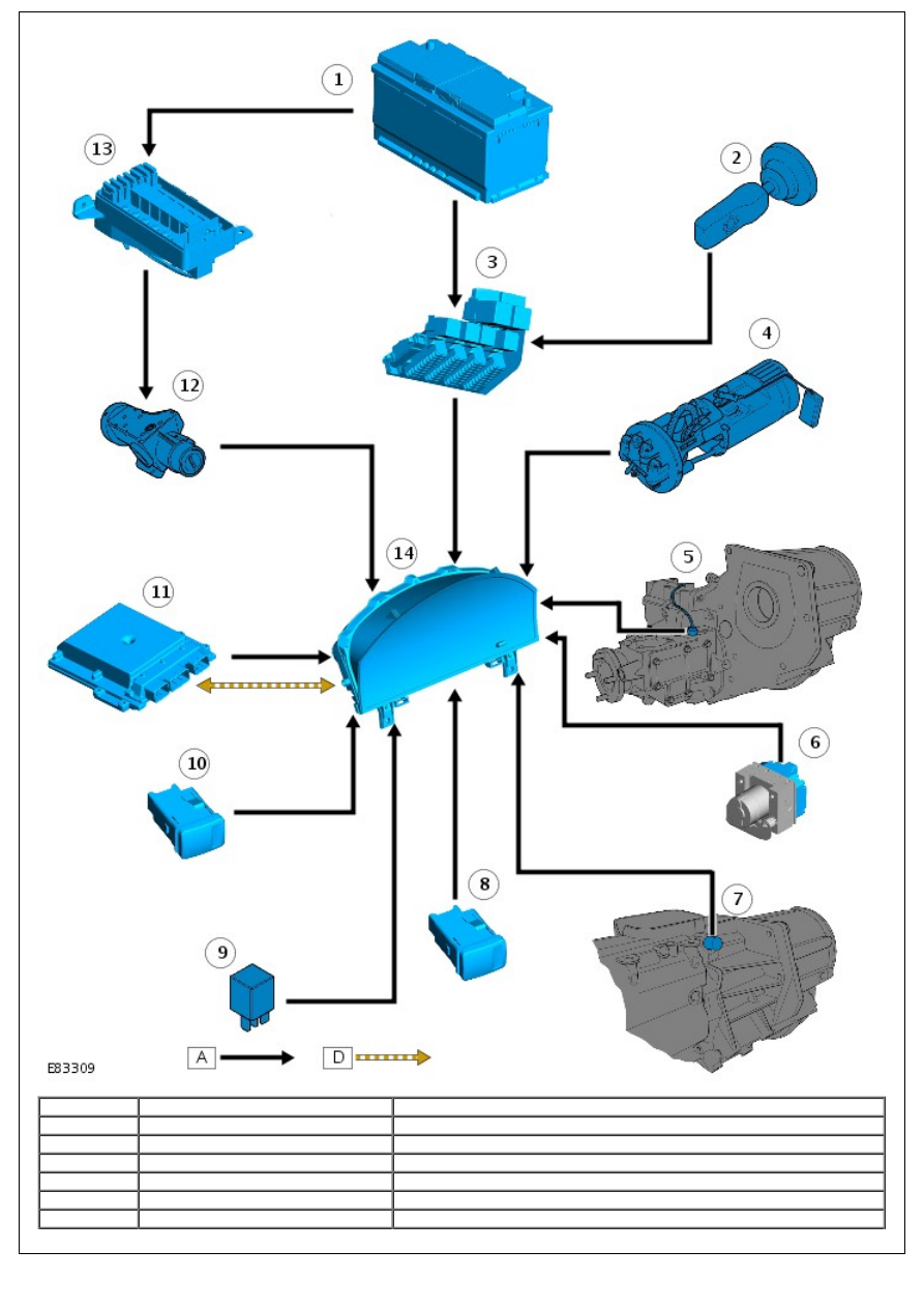
1
-
Battery
2
-
Lighting switch
3
-
central junction box (CJB)
4
-
Fuel tank unit
5
-
Differential lock switch
6
-
ABS module

7
-
Reverse gear switch
8
-
Hazard flasher switch
9
-
Hazard flasher relay
10
-
Heated rear screen switch
11
-
ECM
12
-
Ignition switch
13
-
battery junction box (BJB)
14
-
Instrument cluster
CONTROL DIAGRAM - SHEET 2 OF 2
• NOTE: A = Hardwired
Item
Part Number
Description
1
-
Heated windshield timer unit
2
-
Anti-theft alarm control module
3
-
Vehicle speed sensor
4
-
High/Low range switch
5
-
Column switch - turn signal indicators
6
-
Rear fog lamp switch

7
-
Brake fluid level switch
8
-
Parking brake switch
9
-
Instrument cluster
PRINCIPLES OF OPERATION
Speedometer
The instrument cluster receives a hardwired vehicle speed signal from the vehicle speed sensor. The vehicle speed
sensor is a Hall effect sensor located on the transfer box. The sensor acts on a reluctor ring located on the transfer box
rear output shaft.
For additional information, refer to:
Transfer Case - Vehicles With: 6-Speed Manual Transmission - MT82
(308-07A
Transfer Case - 2.4L Duratorq-TDCi HPCR (103kW/140PS) - Puma, Description and Operation).
Tachometer
The tachometer is driven by an engine speed signal transmitted on the high speed CAN bus from the ECM. The signal is
derived from the crankshaft position (CKP) sensor. The signal is received by the instrument cluster microprocessor and
the output from the microprocessor drives the tachometer.
Fuel Level Gauge
The instrument cluster calculates the amount of fuel in the tank by providing a reference current to the fuel tank level
sensor. The fuel tank level sensor uses a float operated MAgnetic Passive Position Sensor (MAPPS) for measuring fuel
tank contents.
The instrument cluster measures the returned output from the sensor, which is proportional to the level of the float arm
and consequently the amount of fuel in the tank. The instrument cluster monitors the signal from the sensor at
approximately 20 second intervals. This prevents the gauge needle pointer from continually moving due to the
movement of fuel in the tank when cornering or braking.
Engine Coolant Temperature Gauge
The ECT gauge is driven by high speed CAN bus messages from the ECM. For normal operating temperatures the gauge
needle pointer is positioned centrally in the gauge display. The needle pointer position translates to the following
approximate temperatures.
Engine Coolant Temperature °C (°F)
Needle Pointer Position
Ignition off
Park position
40 (104)
Cold (blue segment)
75 - 115 (167 - 239)
Normal (central)
120 (248)
Start of hot (red segment)
125 (257)
End of hot
Glow Plugs Active Indicator
The glow plugs active indicator is illuminated by the instrument cluster software on receipt of a high speed CAN bus
message from the ECM. The indicator illuminates in an amber color when the ignition is turned to position II. The
indicator illumination period varies with ECT and if ECTis high, will not illuminate.
The indicator is controlled by high speed CAN bus messages from the ECM, which equate to the time the glow plugs are
energized to pre-heat the combustion chambers. When the glow plug heating time is complete, the indicator is
extinguished indicating to the driver that the engine can now be started.
Safety Belt Indicator
The safety belt indicator is controlled by a hardwired feed from switches located in the front seat safety belt buckles.
The safety belt indicator is fitted to Gulf specification vehicles only.
Malfunction Indicator Lamp
The MIL is controlled by the instrument cluster software on receipt of a high speed CAN bus message from the ECM. The
lamp is illuminated for a bulb check by the ECM when the ignition is moved to position II. The lamp is extinguished
when the engine starts.
If the MIL remains illuminated after the engine is started or illuminates while driving, a fault is present and must be
investigated at the earliest opportunity. Illumination of the MIL indicates there is an on-board diagnostic (OBD) fault
which will cause excessive emissions output.
Left and Right Turn Signal Indicators
The turn signal indicators are controlled by the instrument cluster software on receipt of hardwired signals from the
steering column switch. When the turn signal indicator switch is operated, the instrument cluster receives a signal feed
from the column switch. The instrument cluster software controls the flash rate of the indicator which flashes in a green
color. During normal turn signal indicator operation the indicator flashes slowly, accompanied simultaneously by a sound
from the instrument cluster sounder. If a fault exists, the instrument cluster flashes the indicator at double speed.
High Engine Coolant Temperature Indicator
The high ECT indicator is illuminated on receipt of a high speed CAN bus message from the ECM. The indicator
illuminates when the ignition is turned to position II for a 3 second bulb check and is extinguished when the engine is
started. If the indicator illuminates while driving, a fault in the engine cooling system has become present and the
engine must be stopped at the earliest opportunity.
High Beam Indicator
The high beam indicator is controlled by the instrument cluster software on receipt of a hardwired signal from the CJB.
The signal from the CJB originates from the steering column switch when high beam is selected.
Hazard Flasher Indicator
The hazard flasher indicator is controlled by the instrument cluster software on receipt of a hardwired signal from the
hazard flasher switch. The hazard flasher indicators can operate with the ignition switched off, flashing both the left and
right turn signal indicators simultaneously.
Traction Control Indicator
The traction control indicator is illuminated by the instrument cluster software on receipt of a hardwired signal from the
ABS module. The indicator is illuminated for 3 seconds for a bulb check when the ignition switch is turned to position II.
If no fault exists, the indicator is extinguished after the bulb check period.
When traction control is active, the indicator flashes to inform the driver that the system is regulating engine output.
Heated Windshield Indicator
In order for the heated windshield to operate, the engine must be running. The instrument cluster receives an engine
running signal from the ECM over the high speed CAN bus. On receipt of this message, the instrument cluster provides a
hardwired signal to the heated windshield timer relay. If heated windshield operation is subsequently requested a
ground path is created via the heated windshield switch. When the instrument cluster registers the ground, it illuminates
the heated windshield indicator.
Differential Lock Indicator
The differential lock indicator is illuminated on receipt of a hardwired signal from the differential lock switch. The
indicator will illuminate at all times when the differential lock is selected and the ignition switch is in position II.
Rear Fog Lamp Indicator
The rear fog lamp indicator is illuminated on receipt of a hardwired signal from the rear fog lamp switch. The indicator
will illuminate at all times when the rear fog lamps are selected on and the ignition switch is in position II.
Trailer Indicator
The trailer indicator is controlled by the instrument cluster software on receipt of a hardwired signal from the hazard
flasher relay. When a trailer is connected, the hazard flasher relay energizes and provides a feed to the instrument
cluster. The feed across the hazard flasher relay originates from the steering column switch. The instrument cluster
software controls the flash rate of the indicator which flashes in a green color. The trailer indicator flashes slowly,
accompanied simultaneously by a chime from the instrument cluster sounder, at the same rate as the turn signal
indicators.
Low Fuel Indicator
The instrument cluster calculates the amount of fuel in the tank by providing a reference current to the fuel tank level
sensor. If the cluster determines the level of fuel within the tank is at or below 14 liters (3.69 gallons) it will illuminate
the low fuel indicator and emit a single chime. For more information, refer to 'Fuel Level Gauge' above.
ABS Indicator
The ABS indicator is controlled by the ABS module which transmits a hardwired signal to the instrument cluster. The
indicator is illuminated in an amber color for a 3 second bulb check by the ABS module when the ignition is turned to
position II. If the indicator remains illuminated or illuminates when driving, an ABS fault has occurred and the ABS
function will not be available.
The ABS module will alert the driver that a diagnostic trouble code (DTC) has been stored in its memory during the bulb
check process. It will do this by;
illuminating the indicator for 0.5 seconds
extinguishing the indicator for 0.5 seconds
illuminating the indicator for 2 seconds.
If the indicator is illuminated for a sensor fault, the indicator will remain illuminated at the next ignition cycle, even if
the fault is rectified. When the vehicle is driven above a speed of 20 km/h (12.5 mph) the indicator will be extinguished.
This allows the ABS module to perform a thorough check of the system and to establish that the output from the
replaced sensor is correct.
Нет комментариевНе стесняйтесь поделиться с нами вашим ценным мнением.
Текст