Defender. Manual — part 215
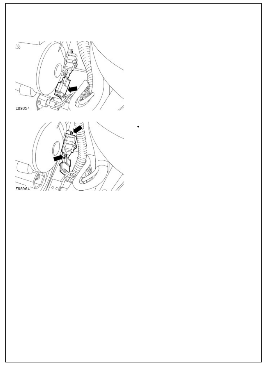
Control Components - Blower Motor Resistor
Removal and Installation
Removal
1. Disconnect the electrical connector.
2. Remove the blower motor resistor.
Remove the 2 screws.
Installation
1. To install, reverse the removal procedure.
Instrument Cluster -
Torque specifications
Discription
Nm
lb.ft
Instrument cluster
2
1
Instrument cluster upper finisher
2
1
Instrument cluster lower finisher
2
1
Instrument Cluster - Instrument Cluster
Description and Operation
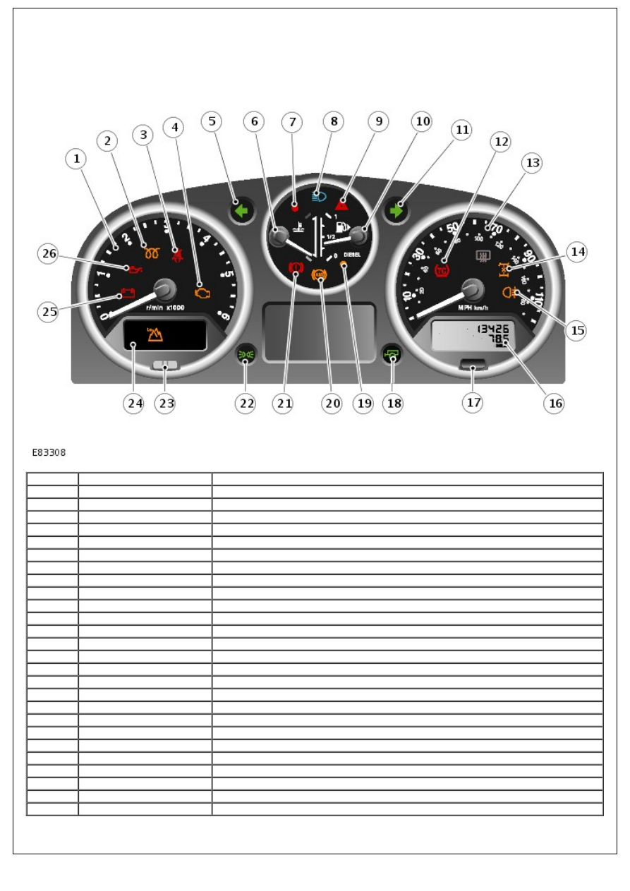
COMPONENT LOCATION
Item
Part Number
Description
1
-
Tachometer
2
-
Glow plugs active indicator
3
-
Safety belt indicator (Gulf States only)
4
-
malfunction indicator lamp (MIL)
5
-
Left turn signal indicator
6
-
engine coolant temperature (ECT) gauge
7
-
High ECT indicator
8
-
High beam indicator
9
-
Hazard flasher indicator
10
-
Fuel level gauge
11
-
Right turn signal indicator
12
-
Traction control indicator
13
-
Speedometer
14
-
Differential lock indicator
15
-
Rear fog lamp indicator
16
-
Odometer and trip meter display
17
-
Trip reset button
18
-
Trailer indicator
19
-
Low fuel indicator
20
-
anti-lock brake system (ABS) indicator
21
-
Brake warning indicator
22
-
Side lamps on indicator
23
-
Anti-theft alarm indicator
24
-
Transfer box low range indicator
25
-
Ignition/No charge indicator
26
-
Low oil pressure indicator
OVERVIEW
The instrument cluster is located in the instrument panel, above the steering column. The instrument cluster comprises
analogue gauges and a number of indicator lamps to display system status.
ANALOGUE GAUGES
The analogue gauges located in the instrument cluster are as follows:
Speedometer
Tachometer
Fuel level gauge
ECT gauge.
Each analogue gauge is driven by an electronic stepper motor. The characteristics of this type of motor produce
damping of the pointer needle. All gauges return to their respective zero positions when the ignition is switched off.
INDICATOR LAMPS
Indicator lamps are located in various positions in the instrument cluster and can be split into 2 groups; self controlled
and externally controlled.
Self controlled indicators are dependent on software logic within the instrument cluster for activation.
Externally controlled indicators are supplied with current from their respective systems. Engine related externally
controlled indicators are illuminated by the instrument cluster on receipt of a high speed controller area network (CAN)
bus message from the engine control module (ECM).
The following table shows the available indicators and indicates if they are subject to an indicator check at ignition on
and if they are self or externally controlled.
Indicator Lamp
Illumination
Color
Bulb Check
Self Controlled (S)/Externally
Controlled (E)
Glow plugs active Amber
No (may illuminate at ignition on to show glow
plugs active)
E
Safety belt
Red
No
E
MIL
Amber
* Yes
E
Left turn signal
Green
No
E
High ECT
Red
Yes
S
High beam
Blue
No
E
Hazard flasher
Red
No
E
Right turn signal Green
No
E
Traction control
Amber
Yes
E
Differential lock
Amber
No
E
Rear fog lamp
Amber
No
E
Trailer
Green
No
E
Low fuel
Amber
Yes
S
ABS
Amber
* Yes
E
Brake warning
Red
Yes
E
Side lamps on
Green
No
E
Anti-theft alarm
Red
No
E
Transfer box low
range
Green
No
E
Ignition/No
charge
Red
No
E
Low oil pressure Red
No
E
* = Bulb check performed by sub-system module, not instrument cluster
CONTROL DIAGRAM - SHEET 1 OF 2
• NOTE: A = Hardwired; D = High speed CAN bus
Нет комментариевНе стесняйтесь поделиться с нами вашим ценным мнением.
Текст