Defender. Manual — part 217
Brake Warning Indicator
The brake warning indicator is illuminated for a 3 second bulb check when the ignition is turned to position II. The
indicator will also illuminate if the parking brake is on, or the brake fluid falls below a pre-determined level. The
instrument cluster is hardwired to the parking brake switch and the brake fluid level switch, which are connected in
parallel. If either of the conditions above are met a ground path is created, illuminating the indicator.
Side Lights On Indicator
The side lights on indicator is controlled by the lighting switch. When the lighting switch is turned to the side or
headlamp position, a hardwired feed is provided to the instrument cluster via the CJB. On receipt of the hardwired feed,
the instrument cluster illuminates the indicator.
Anti-theft Alarm Indicator
Illumination of the anti-theft alarm indicator is controlled directly by the anti-theft alarm control module. For additional
information, refer to:
Anti-Theft - Active
(419-01A Anti-Theft - Active, Description and Operation),
Anti-Theft - Passive
(419-01B Anti-Theft - Passive, Description and Operation).
Transfer Box Low Range Indicator
The transfer box high/low range switch is hardwired to the instrument cluster. When low range is selected, the transfer
box provides a feed to instrument cluster, which subsequently illuminates the green low range indicator. The low range
indicator remains permanently illuminated until high range is selected and the feed from the high/low range switch is
removed.
Ignition/No Charge Warning Indicator
The ignition/no charge indicator is controlled by the instrument cluster software and illuminated on receipt of a high
speed CAN bus message from the ECM. The indicator illuminates in a red color when the ignition is turned to position II
and is extinguished when the engine is started.
If the indicator remains illuminated after the engine has started or illuminates when driving, the alternator charge
output has failed.
Low Oil Pressure Warning Indicator
The low oil pressure indicator is controlled by the instrument cluster software and illuminated on receipt of a high speed
CAN bus message from the ECM. The indicator is illuminated in a red color when the ignition switch is turned to position
II. When the engine is started and the oil pressure increases the low oil pressure indicator should extinguish. If the
indicator remains illuminated or illuminates when driving the vehicle should be stopped at the earliest opportunity and
the engine switched off until the fault is rectified.
Instrument Cluster Replacement
If a new instrument cluster is to be fitted, the Land Rover approved diagnostic system must be connected to the vehicle
and the instrument cluster renewal procedure run. This will ensure that vehicle coding data is correctly installed in the
new instrument cluster. The Land Rover approved diagnostic system will also record the current service interval data
and restore the settings to the new instrument cluster.
Instrument Cluster - Instrument Cluster
Diagnosis and Testing
Overview
The instrument cluster is a totally electronic device which receives analogue or digital signals via hardwired or bus
system for instrumentation operation. The signals which are processed by the engine control module (ECM) are
transmitted via controller area network (CAN) to the instrument cluster and displayed as analogue gauge indications or
warning lamp illuminations. The instrument cluster is connected to the vehicle electrical system by one connector which
provides all input and output connections. No components of the instrument cluster are serviceable. The instrument
cluster has two main functions to provide information to the driver of the vehicle status and to process and relay digital
signals. The instrument cluster identifies the signals and displays the appropriate message in the message center. For
information on the operation of the systems:
REFER to:
Instrument Cluster
(413-01 Instrument Cluster, Description and Operation) /
Communications Network
(418-00 Module Communications Network, Description and Operation).
Car Configuration File (CCF)
CAUTION: If a new instrument cluster is to be installed, the instrument cluster renewal procedure must be carried
out using the approved diagnostic system. This will make sure that the car configuration file (CCF) data is correctly
transferred from the ECM to the replacement instrument cluster. The CCF will also need to be updated using the
approved diagnostic system if the vehicle is modified in service from its original factory specification. This can include
the fitting of non-standard wheels and/or tires and optional dealer fit accessory components with an electrical interface,
such as parking aid.
The CCF contains all relevant data about the specification and market condition of the applicable vehicle, immobilization
codes and driver personal settings. This information is retained in the ECM and the instrument cluster enabling each
system module to detect which systems and components are fitted to the vehicle. The information is continuously
transferred between these two system modules to make sure that the data is constantly backed-up between the
modules.
Inspection and Verification
1. 1. Verify the customer concern.
2. 2. Confirm which, if any, warning lights were displayed on the instrument cluster.
3. 3. Visually inspect for obvious electrical faults.
Visual inspection
Electrical
Battery and passenger junction box fuses
Read diagnostic trouble codes (DTCs)
- Using the approved diagnostic system or a scan tool
Damaged, loose or corroded connectors
Instrument cluster for any external damage
Electrical circuits
4. 4. If an obvious cause for an observed or reported concern is found, correct the cause (if possible) before
proceeding to the next step.
5. 5. Use the approved diagnostic system or a scan tool to retrieve any DTCs before moving onto the DTC index.
Make sure that all DTCs are cleared following rectification.
DTC Index
• NOTE: If a control module or component is suspect and the vehicle remains under manufacturer warranty, refer to the
Warranty Policy and Procedures manual (section B1.2), or determine if any prior approval program is in operation,
before the replacement of a component.
• NOTE: Generic scan tools may not read the codes listed, or may read only 5-digit codes. Match the 5 digits from the
scan tool to the first 5 digits of the 7-digit code listed to identify the fault (the last 2 digits give extra information read
by the manufacturer-approved diagnostic system).
• NOTE: When performing voltage or resistance tests, always use a digital multimeter (DMM) accurate to three decimal
places, and with an up-to-date calibration certificate. When testing resistance always take the resistance of the DMM
leads into account.
• NOTE: Check and rectify basic faults before beginning diagnostic routines involving pinpoint tests.
• NOTE: Inspect connectors for signs of water ingress, and pins for damage and/or corrosion.
• NOTE: If DTCs are recorded and, after performing the pinpoint tests, a fault is not present, an intermittent concern
may be the cause. Always check for loose connections and corroded terminals.
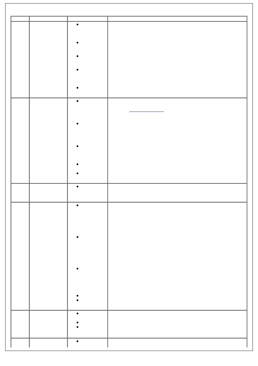
DTC
Description
Possible cause(s)
Action
U000188 High speed
controller area
network (CAN) bus
off fault
CAN circuit:
short circuit
to each
other
CAN circuit:
short circuit
to power
CAN circuit:
short circuit
to ground
Engine
control
module
(ECM) fault
Instrument
cluster fault
Carry out a complete vehicle read for DTCs indicating a CAN circuit or
module fault. Rectify as necessary. Clear the DTCs and test for normal
operation. Refer to the warranty policy and procedures manual if a
module is suspect.
B1A7501 Fuel sender 1-
general electrical
error
Fuel level
sender
circuit: short
circuit to
ground
Fuel level
sender
circuit: short
circuit to
power
Fuel level
sender
circuit: open
circuit
Fuel sender
fault
Instrument
cluster fault
Check the fuel level sender and circuits. Refer to the electrical guides.
Install a new fuel level sensor if necessary,
REFER to:
Fuel Level Sender
(310-01 Fuel Tank and Lines - 2.4L
Duratorq-TDCi HPCR (103kW/140PS) - Puma, Removal and
Installation).
. Clear the DTCs and test for normal operation. Refer to the warranty
policy and procedures manual if the instrument cluster is suspect.
B1A8164 Internal trip switch
plausibility fault
Instrument
cluster fault
Check the instrument cluster circuits. Refer to the electrical guides.
Clear the DTC. Cycle the ignition and retest. If the DTC resets, suspect
the instrument cluster. Refer to the warranty policy and procedures
manual if the instrument cluster is suspect.
P160231 Immobilizer/engine
control module
(ECM)
communication
error – no signal
Alarm
(immobiliser)
- instrument
cluster
circuit: short
circuit to
ground
Alarm
(immobiliser)
- instrument
cluster
circuit: short
circuit to
power
Alarm
(immobiliser)
- instrument
cluster
circuit: open
circuit
ECM fault
Instrument
cluster fault
Check for related DTCs. Rectify as necessary. Clear the DTCs and test
for normal operation. Check the alarm (immobilizer) circuits. Refer to
the electrical guides. Rectify as necessary. Clear the DTCs and test for
normal operation. Refer to the warranty policy and procedures manual
if a module is suspect.
U010087 Lost controller
area network
(CAN)
communication –
engine control
module (ECM)
CAN circuit:
open circuit
ECM fault
Instrument
cluster fault
Carry out a complete vehicle DTC read. Check for other CAN DTCs or
apparently unrelated customer complaints. Check the CAN and module
power and ground circuits. Refer to the electrical guides. Rectify as
necessary. Clear the DTCs and test for normal operation. Refer to the
warranty policy and procedures manual if a module is suspect.
U040168 Invalid data
received from
Incorrect
signals
Check for related DTCs. Rectify as necessary. Clear the DTCs and test
for normal operation. Check the sensor signal circuits. Refer to the
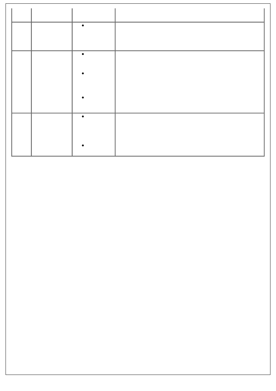
engine control
module (ECM)
received
from ECM
electrical guides. Rectify as necessary. Clear the DTCs and test for
normal operation.
U210100 Control module
configuration
incompatible
Central car
configuration
parameter
missing or
corrupted
Check correct central car configuration software is installed.
Reprogramme the instrument cluster as necessary.
U300017 Control module
over voltage
Vehicle
started using
a booster
pack
Supply
voltage has
exceeded
17.4v for 12
seconds
Charging
system over
charging
Check the instrument cluster supply circuits. Check the charging
system and charging voltage. Refer to the electrical guides. Rectify as
necessary. Clear the DTC. Cycle the ignition and retest. Refer to the
warranty policy and procedures manual if the instrument cluster is
suspect.
U300046 Control module
electrically
eraseable
programmable
read only memory
(EEPROM) error
Power supply
lost from the
instrument
cluster with
the ignition
on
Instrument
cluster fault
Check the instrument cluster circuits. Refer to the electrical guides.
Rectify as necessary. Clear the DTC. Cycle the ignition and retest.
Configure the module using the approved diagnostic system. If the
DTC resets suspect the instrument cluster. Refer to the warranty
policy and procedures manual if the instrument cluster is suspect.
Нет комментариевНе стесняйтесь поделиться с нами вашим ценным мнением.
Текст