Defender (1993+). Manual — part 47
LT77S
MANUAL GEARBOX
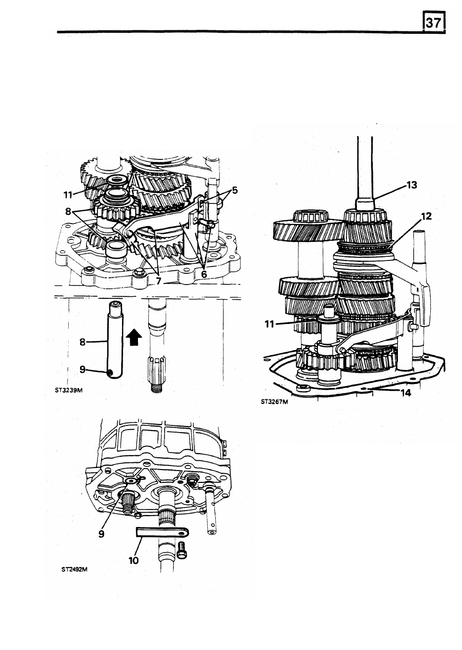
4.
Fit layshaft while lifting mainshaft to clear
10.
Secure reverse shaft with manufactured tool
5.
Turn selector shaft and interlock spool to
11.
Fit reverse gear thrust washer to shaft.
allow reverse lever to engage spool flange.
6.
Fit reverse lever
to
pivot post and secure with
pin and circlip.
7.
Fit slipper pad to lever.
gasket.
8. Fit reverse gear shaft, spacer and gear.
9. Fit slipper to
reverse
gear and ensure roll pin
in
shaft engages
in slot in
centre plate.
layshaft rear bearing.
"A".
12.
Fit fourth gear baulk ring.
13.
Lubricate spigot bearing and
fit
input shaft.
14.
Remove centre plate workstand bolt and fit
REISSUED: FEB 1993
29
LT77S MANUAL
GEARBOX
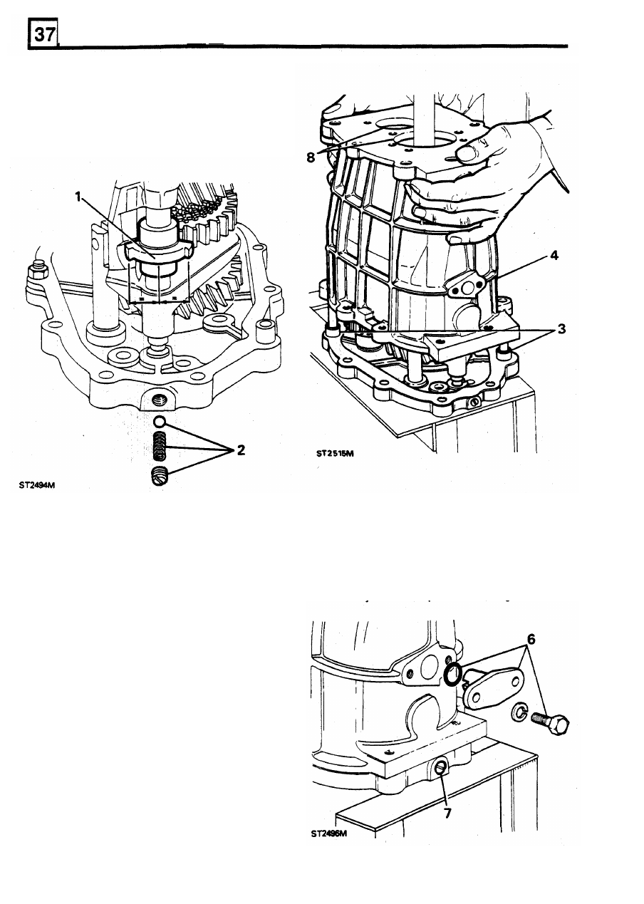
FITTING
GEARBOX
CASING
1.
Turn selector shaft and spool to neutral
2.
Fit out-board detent ball and spring and
position.
secure with plug.
CAUTION: Do not use force to fit retainer.
Provided the spool has not been disturbed the
retainer will slide into position. If not, remove the
gear case and reposition spool or shaft.
3. Fit guide studs to casing and check oil scoop
is correctly fitted.
4. Without using force, fit gearcase.
NOTE: Ensure that the centre plate dowels and
selector shaft are properly located.
7. Remove detent plug, apply Loctite 290 or
Hylomar PL 32 to thread, refit and stake.
8
Fit layshaft and input shaft bearing tracks.
5. Secure centre plate and gearcase to
workstand with two 8 x 35mm bolts.
6. Apply PL 32 to joint face and bolt threads and
fit spool retainer.
30
REISSUED: FEB 1993

LT77S MANUAL GEARBOX
FITTING
FIFTH GEAR
CAUTION: Since the fifth gear is a tight fit on the
layshaft, the force, when pressing the gear, must
not be transferred to the layshaft front bearing.
Tool "D" and packing disc should be made to the
dimensions given to absorb the force. The plate
also retains the input shaft bearing outer track.
4.
Fit a new stake nut but
do
not
tighten.
5.
Fit
fifth gear assembly to mainshaft.
1.
Secure Tool
"D" with two 8x25mm bolts.
Insert disc between Tool "D" and layshaft.
2.
Release and invert gearbox and remove
reverse shaft retainer plate.
3.
With the extraction groove uppermost, drive
fifth gear on to layshaft using
18G
1422.
REISSUED:
FEB
1993
31
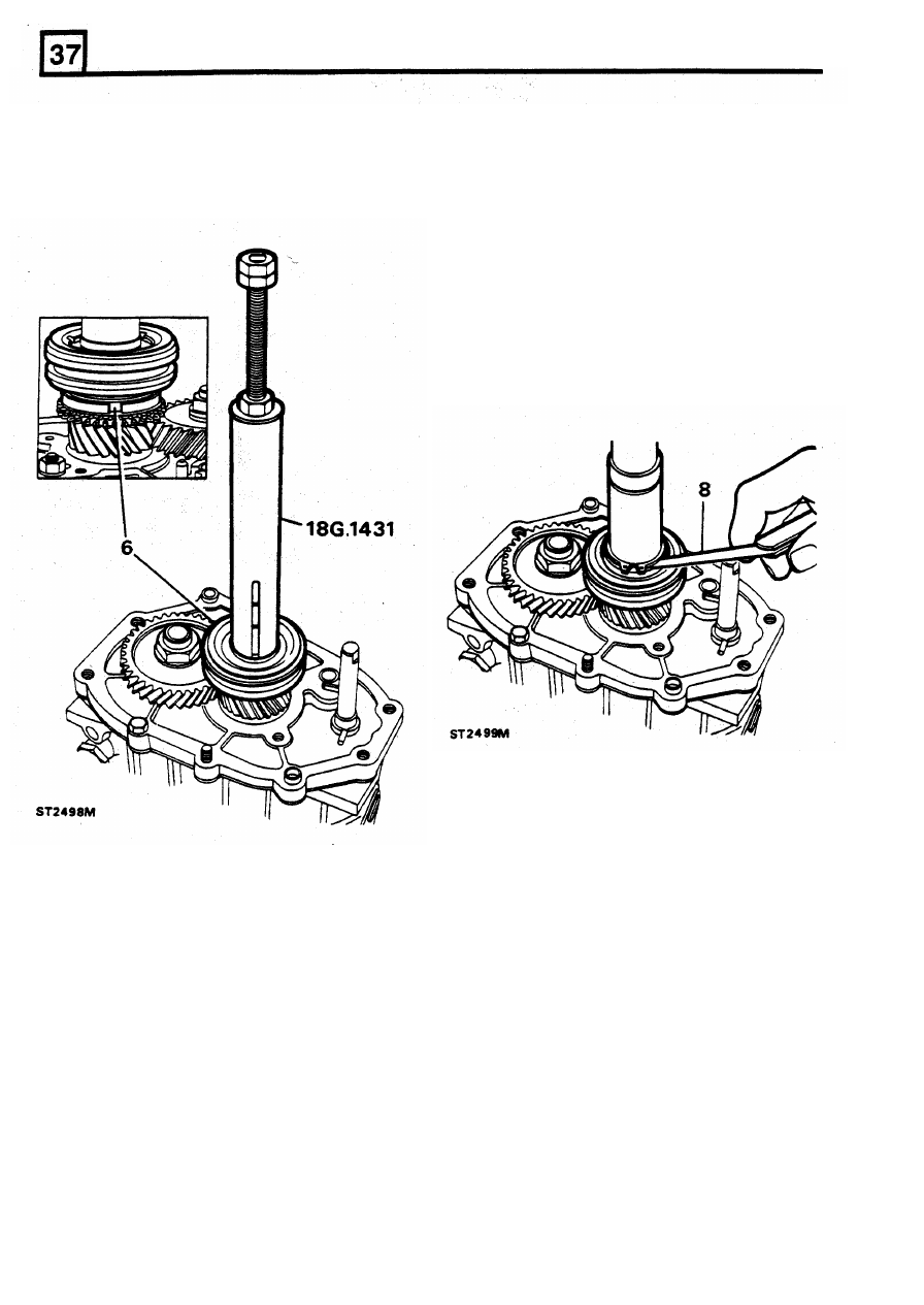
LT77S MANUAL GEARBOX
6.
Press
fifth
gear synchromesh assembly
to
Part number
Thickness
mainshaft using 18G 1431.
FRC 5284
5,10
CAUTION: Before pressing the assembly fully
FRC 5286
5,16
home, ensure that the slipper
pads locate in the
FRC 5288
5,22
baulk ring slots.
FRC 5290
5,38
FRC 5292
5,34
FRC 5294
5,40
FRC 5296
5,46
FRC 5298
5,52
FRC 5300
5,58
FRC 5302
5,64
7. Fit the thinnest washer and secure with circlip.
8. Measure clearance between circlip and
washer.
9. Tighten layshaft stake nut using 18G 1205.
CAUTION: The practice of locking gears to
provide a restraint to tighten the nut is not
acceptable due to
high torque figure required.
NOTE:
Only
limited
movement
of
the
synchromesh inner member on the main-shaft i s
permissable. The maximum clearance i s 0,005mm
t o 0,055mm (0.0002in
to
0.002in) and t o achieve
this
the following selective washers are available.
32
REISSUED: FEB 1993
Нет комментариевНе стесняйтесь поделиться с нами вашим ценным мнением.
Текст