Defender (1993+). Manual — part 48
LT77S
MANUAL GEARBOX
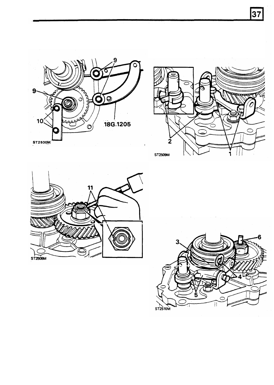
10.
Secure
tool
“A“
to
gear and gear case and
using a suitable torque wrench tighten the
nut
to
the correct torque.
FIFTH
GEAR SELECTOR FORK ASSEMBLY
1.
Fit fifth gear selector fork bracket.
2.
Fit the fifth gear spool long end towards
centre plate.
11.
Using a round nose punch, form the collar into
the layshaft
slots.
3.
Fit slippers to selector fork.
4.
Fit fork to synchromesh and secure with pins
and
“E” clips.
NOTE: Before fitting pins and clips cover holes
in centre plate to prevent them falling into
casing.
5. Engage tongue
of
spool in selector fork.
6.
Fit oil pump drive
to
layshaft.
REISSUED:
FEB
1993
33
LT77S
MANUAL GEARBOX
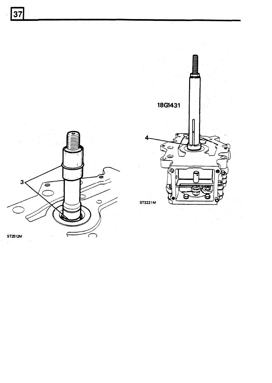
EXTENSION CASE
1. Release centre plate from workstand and fit
gasket on joint face.
2. Fit extension case while aligning oil pick-up
pipe. Remove guide studs and secure to main
case.
NOTE:
Do not use farce,
if necessary remove
case and re-align
oil
pump drive
if case does not
fit first time.
CAUTION:
To protect "O" ring while fitting, cover
mainshaft
splines with smooth tape.
3. Fit " O " ring to mainshaft groove.
4. Fit “O” ring collar to mainshaft using 18G
1431.
34
REISSUED: FEB
1993
LT77S MANUAL GEARBOX
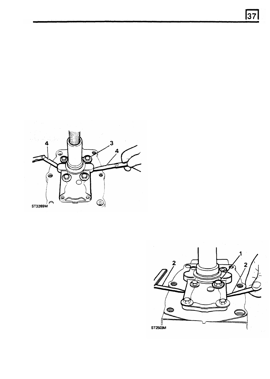
INPUT-MAINSHAFT BEARING ADJUSTMENT
Mainshaft selective washers
1 .
Turn gearbox over with input shaft uppermost.
Part number
Thickness(mm)
Remove layshaft support plate.
FRC 4327
1,51
NOTE: Correct shimming of the input shaft
FRC 4329
1,57
bearing is vital to ensure that the mainshaft
FRC 4331
1,63
assembly has the design intended end float,
and
FRC 4333
1,69
FRC 4337
1,81
2. Measure the thickness of a new front cover
FRC 4339
1,87
the bearings are not pre-loaded.
FRC 4335
1,75
gasket.
FRC 4341
1,93
3. Place the original shim on mainshaft bearing
FRC 4343
1,99
and finger tighten the bolts.
FRC 4345
2,05
4. Measure the clearance between front cover
FRC 4347
2,11
FRC 4349
2,17
and gearcase with
two
feeler gauges.
FRC 4351
2,23
FRC 4353
2,29
FRC 4355
2,35
FRC 4357
2,41
FRC 4359
2,47
FRC 4361
2,53
FRC 4363
2,59
FRC 4365
2,65
FRC 4367
2,67
FRC 4369
2,77
LAYSHAFT BEARING ADJUSTMENT
1.
Place original selective washer on layshaft
bearing,
fit
front cover without gasket, and
finger tighten bolts.
2. Measure clearance, with
two
feeler gauges,
between cover and gearcase. Select a shim
that will provide a clearance
equal to the
thickness
of the gasket that was selected and
measured when calculating the adjustment of
5.
I
I
f
r
e
q
u
i
r
e
d
,
If required,
change the selective washer to
provide a clearance of 0,35mm to 0,085mm
(0.001 to 0.003ins) less than the gasket
the input and mainshaft bearing.
thickness.
NOTE: This will ensure that when the gasket and
cover
is fitted
to
the correct torque, the
input
and mainshaft bearings will have no pre-load and
not more than 0,06mm (0.0025in) end float.
6. Remove front cover and keep gasket and
selective washer together.
REISSUED: FEB 1993
35
LT77S
MANUAL GEARBOX
NOTE: This will ensure zero layshaft bearing end
GEAR LEVER AND REMOTE HOUSING
float and not more than 0,025mm (0.001in)
ASSEMBLY
pre-load once the cover and gasket are fitted and
bolts correctly torqued.
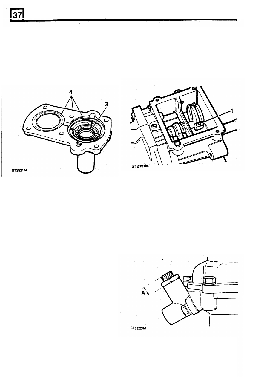
3. Remove cover and selected washer and
fit
4. Fit mainshaft and layshaft selected washers
to neutral
position.
1.
Fit
quadrant to selector shaft with new roll pin,
NOTE: Push shaft forward, fit quadrant
so
ledge
is
to
the left viewing
box
from rear. Return shaft
new oil seal, lip towards gearcase.
and gasket.
2. With a new gasket,
fit
remote housing locating
5 . Wrap protective tape round input shaft splines.
over dowels.
6. Apply Hylomar
PL
32 to bolt threads and
secure cover.
NOTE: Ensure rollers locate
in quadrant fork.
Layshaft selective washers.
3. Fit transfer gear change housing.
Part number
Thickness(mm)
Reverse gear plunger adjustment.
FTC 0262
1,36
1.
Fit plunger with original shims and tighten
FTC 0264
1,42
bolts.
FTC 0266
1,48
2. Slacken locknut, turn adjuster screw
so that
FTC 0268
1.54
dimension
“A”
is approximately 12 rnm
(0.50
FTC 0270
1,60
in). Tighten locknut.
FTC 0272
1,66
FTC 0274
1,72
FTC 0276
1,78
FTC
0278
1,84
FTC 0280
1,90
FTC 0282
1,96
FTC 0284
2,02
FTC 0286
2,08
FTC
0288
2,14
FTC 0290
2,20
FTC 0292
2,26
FTC 0294
2,32
FTC 0296
2,38
36
REISSUED:
FEB
1993
Нет комментариевНе стесняйтесь поделиться с нами вашим ценным мнением.
Текст