Defender (1993+). Manual — part 96
AIR CONDITIONING
CONDENSER
AND
RECEIVER/DRIER
Removal
1.
Place the vehicle in a well ventilated area.
2.
Stop the engine, open and secure the bonnet.
3.
Remove the caps from the compressor
service valves. Connect the gauge set for
evacuation, and evacuate as detailed earlier.
4.
Having evacuated the air conditioning system,
open fully (turn anti-clockwise) the compressor
service valves and disconnect the gauge set.
Replace all caps to valve connections.
5.
Release the four top and two side fixings
securing the grille and nose assembly and
remove.
6.
Disconnect the wires at the rear of the horn,
the air conditioning fan leads located across
the top of the fan cowling frame and the
electrical connector to the receiver/drier.
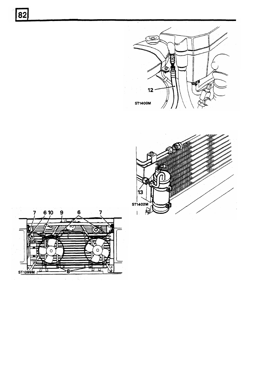
7. Release the four bolts and large packing
washers securing the cowling
to
the wing
sides.
8.
Remove the four nuts securing the fan
cowling to the bottom bracket and lift clear.
9.
Remove the two bolts securing the bonnet
striker support plate.
13.
Release the high pressure pipe from the
receiver/drier, cap the pipe end connections.
Condenser removal
only
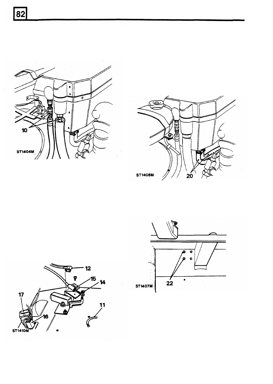
10. Release the top air conditioning hose and cap
the ends to prevent moisture and dirt entering
the system.
14.
Release both air conditioning pipes from the
condenser extension plate. Lift the condenser
clear.
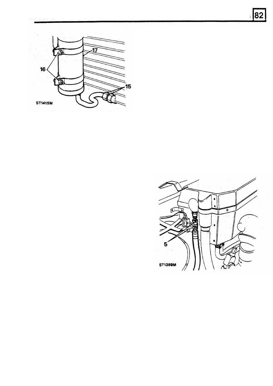
Receiver/drier removal
15.
Whilst supporting with suitable spanners,
unscrew the bottom union to the receiver/drier.
Cap the pipe ends
to
prevent dirt or moisture
entering the system.
16.
Release the receiver/drier clamp bolts and
allow me assembly
to
drop clear of the
lugs and carefully ease the condenser
17. Lift the receiver/drier from the condenser and
forwards as far as possible.
discard. It is
NOT
recommended to refit the
old unit.
11. Lift the condenser from the bottom mounting
condenser.
12.
Release the high pressure air conditioning
hose complete with the sight glass, at the
evaporator connection. Cap the ends to
prevent dirt or moisture entering the system.
18
REISSUED:
FEB
1993
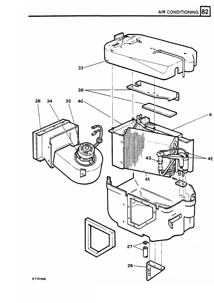
AIR CONDITIONING
EVAPORATOR
NOTE: It
is
only necessary to evacuate the air
conditioning
system
when
removing
the
evaporator matrix or to change the expansion
valve.
Removal
1.
Place the vehicle in a ventilated area away
from open flames and heat sources.
2. Stop the engine and secure the bonnet in an
open position.
Heater matrix and blower motor only
Refitting
3. Remove the caps from the compressor
service valves and close (turn clockwise) fully.
4.
Disconnect the low pressure valve from the
receiver/drier unit.
compressor and cap both ends to prevent dirt
receiver/drier. Using two spanners on each
5.
Using
two
suitable spanners remove the high
union, tighten the union noting that the sight
pressure pipe from the evaporator side. Cap
glass remains in the vertical position.
both ends to prevent dirt or moisture entering
refit the fixings securing the condenser to the
extension plate.
21. Connect and tighten the air conditioning hose
to
the top of the condenser. Use two spanners
on each union.
22. Refit the condenser to the bottom bracket.
23. Place the bonnet striker support plate into
position, do not secure at this stage.
24. Fit the fan cowling support brackets. It will be
necessary to lift the bonnet ‘striker support
plate to permit the positioning of the fan
cowling assembly to the condenser mounting
lugs.
25.
Secure the steady rods and the lower
condenser mounting bracket. Do not tighten
the bolts at this stage. Reconnect the top horn
electrical leads.
26. Loosely fit the four bolts and distance washers
which support the bonnet striker support plate
and fan cowling to the wing sides.
27. Tighten the lower condenser bracket bolts.
28.
Adjust the condenser position with the bonnet
striker support bracket assembly to obtain an
equal distance. from the radiator. Tighten the
four side mounting bolts.
29. Tighten the four nuts and washers which
secure the fan cowling mounting.
30.
Reconnect the electrical wiring for the fan
assemblies, horn and receiver/drier.
31. Recheck the security of all fixings.
entering the system.
32. Refit the front nose and grille assembly and
secure.
33. Evacuate,
sweep
and
charge the
air
conditioning system as previously described.
18. Reverse procedures 15 to 17 using a new
19. Connect the high pressure pipe to the
or moisture entering the system.
20. Carefully locate the condenser into position,
the system.
Evaporator matrix and expansion valve only
6.
Remove the caps from the compressor
service valves and connect the gauge set for
evacuating.
7. Evacuate the air conditioning system as
previously described.
8. Open the compressor service valves and
disconnect the gauge set. Cap all pipes and
gauge connections to prevent dirt or moisture
9. Release the fixings and remove the expansion
tank to provide access to the air conditioning
high and low pressure pipes.
REISSUED:
FEB
1993
19
AIR
CONDITIONING
10,
Whilst supporting both unions with suitable
18.
Remove the screw securing the fuse holder,
then refit both screws to retain
the
resistor
block in the evaporator case.
19. All wiring on the top of the evaporator is now'
disconnected with the exception of the ground
lead, this is disconnected when the evaporator
top fixings are removed.
20. Using suitable pipe clamps, clamp the inlet
and outlet coolant pipes at the base
of
the
evaporator and release the
two
jubilee clips
and detach, or drain the radiator.
spanners unscrew the high and low pressure
air conditioning pipes to the evaporator. Cap
the pipe ends and evaporator inlets to prevent
dirt or moisture entering the system.
Evaporator unit
11.
Disconnect the electrical leads feeding the
compressor clutch cycling switch.
12.
Detach the vacuum pipes from the water
valve switch.
13.
Remove the fixings securing the water valve
switch and withdraw it.
14. Remove the clip and cable connection from
the evaporator heater Rap rod. Use a new clip
on reassembly.
15.
Release the nylon cable retainer.
16.
Detach the resistor block electrical connector.
17.
Remove the relay module from its socket and
remove the self tapping screw to release the
socket.
21. From inside the vehicle remove the front
passenger carpet and self tapping screws
which retain the toe-board. Remove the
toe-board.
22. Release the
two
bolts.
23.
From inside the engine compartment remove
the two bolts from behind the relay module
securing the evaporator to the bulkhead. This
also releases the ground leads.
24. Remove the bolt securing the front of the
evaporator casing.
25. Lift the evaporator clear of the vehicle and
place on a bench with a suitable support
underneath the case
to
ensure the heater
pipes are not damaged.
20
REISSUED:
FEB
1993
REISSUED: FEB
1993
21
Нет комментариевНе стесняйтесь поделиться с нами вашим ценным мнением.
Текст