Defender (1993+). Manual — part 95
AIR
CONDITIONING
7 .
The low side gauge should indicate a vacuum
Sweeping
of 660 mm Hg within five minutes.
8.
Whilst the system
is
evacuating, fill the
NOTE:
This operation
is
in addition
to
charging cylinder by opening the refrigerant
evacuating, and is to remove moisture from
drum valve.
systems that have been open
to
atmosphere for
9. Open the valve at the base of the charging
a
long
period,
or
that are known to contain
cylinder and fill the cylinder with 1,0 kg of
excessive moisture.
refrigerant. Liquid refrigerant will be observed
rising in the sight glass.
1.
Fit a new liquid receiver/drier, as detailed
open the valve at the top of the cylinder
2. Ensure that a full drum of refrigerant is fitted
(behind the control panel) intermittently, to
on the charging and testing equipment.
relieve the head pressure and allow the
3. Fit the charging and testing equipment as
refrigerant to continue filling the cylinder.
previously described for evacuating and
11.
When the refrigerant reaches the desired level
evacuate the air conditioning system, allowing
in the sight glass, close both the valve at the
0,25 to 0,45 kg of refrigerant
to
enter the
base of the cylinder and the valve at the
charging cylinder.
bottom of the refrigerant tank.
4. Close
all
valves on the charging and testing
12. Ensure the top cylinder valve is fully closed.
If
equipment.
bubbling is present in the sight glass, reopen
5. Disconnect the intake hose from the vacuum
equalise the drum and cylinder pressures.
13. If 660 mm Hg of vacuum is not achieved
within five minutes, it signifies either the
system has a leak
or
the vacuum pump is
defective. Initially check the vacuum pump, if
the pump proves
to
be functioning properly
then investigate for a leak in the air
conditioning system.
14.
Close the vacuum control valve No. 3.
15.
Stop the vacuum pump and allow the vacuum
to hold for fifteen minutes, then check that
there is no pressure rise (a
loss
of vacuum)
evident on the compound gauge. Any
pressure rise denotes a leak which must be
rectified before proceeding further. Refer
to
the heading titled ’Leak Detection’ later in this
section.
16. With the system satisfactorily evacuated, the
system is ready for charging with refrigerant.
10.
As the refrigerant stops filling the cylinder,
under the heading “Receiver/Drier”.
the cylinder base valve momentarily to
pump.
6. Connect the intake hose to the valve at the
top of the charging cylinder.
7 .
Open the valve at the top of the charging
cylinder.
8. Put on safety goggles.
9. Crack open the hose connection at valve
No.
3 and allow some refrigerant to purge the
hose, then close the connection.
10. Open the high pressure valve (No.2).
11.
Slowly open valve No. 3, which is now
connected to the top valve of the charging
cylinder, and allow gas
to
flow into the system
until the reading on the compound gauge
remains steady, Between 0,25 and 0,45 kg of
refrigerant will enter the system.
12. Allow the dry refrigerant introduced into the
system
to
remain for 10 minutes.
14
REISSUED: FEB
1993
AIR
CONDITIONING
13. Crack the suction valve charging line at the
6. If
the full charge
of
1,09
kg of liquid refrigerant
service port on the compressor to allow an
will not enter the system, then close the high
escape of refrigerant, at the same time
pressure valve (No.2) and open the low
observing the sight glass in the charging
pressure valve No.1), ensuring that the low
cylinder, A slight drop in the level should be
allowed before closing the connection at the
7.
Start and run the engine at 1,000 -1,500
compressor.
rev/min and allow refrigerant to be drawn
14. Close the high pressure valve (No.2).
though the low pressure valve (No. 1) until the
15.
Close valve No.3.
full charge has been drawn into the system.
16.
Close the valve at the top
of
the charging
8. Close valve No.1.
pressure gauge does not exceed 18.14 kgf².
cylinder.
9. Check the air conditioning system is operating
17. Reconnect
the
charging
and
testing
satisfactorily by carrying out
a
pressure test,
as described later in the Section
equipment, as described for evacuating and
evacuate the air conditioning system.
18. Maintain the vacuum for twenty minutes. The
CAUTION:
Do
not overcharge the air conditioning
air conditioning system is now ready for
system as this
will
cause excessive head
charging with refrigerant.
pressure.
Charging
Leak test
CAUTION:
Do
not charge liquid refrigerant into
the compressor. Liquid cannot
be
compressed;
and
if
liquid refrigerant enters the compressor
sensitive and widely used.
inlet valve, severe damage is possible; in
addition, the oil charge may
be
absorbed into the
1.
Place the vehicle in a well ventilated area but
refrigerant,
causing
damage
when
the
free from draughts, as leakage from the
compressor is operated.
system could be dissipated without detection.
2. Follow the
instructions issued by
the
1.
Fit the charging and testing equipment as
manufacturer of the particular leak detector
previously described for evacuating.
being used. Certain detectors have visual and
2. Evacuate the air conditioning system allowing
audible indicators.
1,09
kg of refrigerant to enter the charging
3. Commence searching for leaks by passing the
cylinder.
detector
probe
around
all
joints
and
3.
Put on safety goggles.
components, particularly on the underside, as
4. Close the low pressure valve (No.1).
the refrigerant gas is heavier than air.
5.
Open the refrigerant control valve (No. 4) and
4. Insert the probe into an air outlet of the
release liquid refrigerant into the system
evaporator. Switch the air conditioning blower
through the compressor discharge valve port
on and off at intervals of ten seconds.
Any
(High pressure). The pressure in the system
leaking refrigerant will be gathered in
by
the
will
eventually balance.
blower and detected.
The following instructions refer to an electronic type
refrigerant leak detector which is the safest, most
REISSUED:
FEB
1993
15
AIR
CONDITIONING
AIR
CONDITIONING
COMPRESSOR
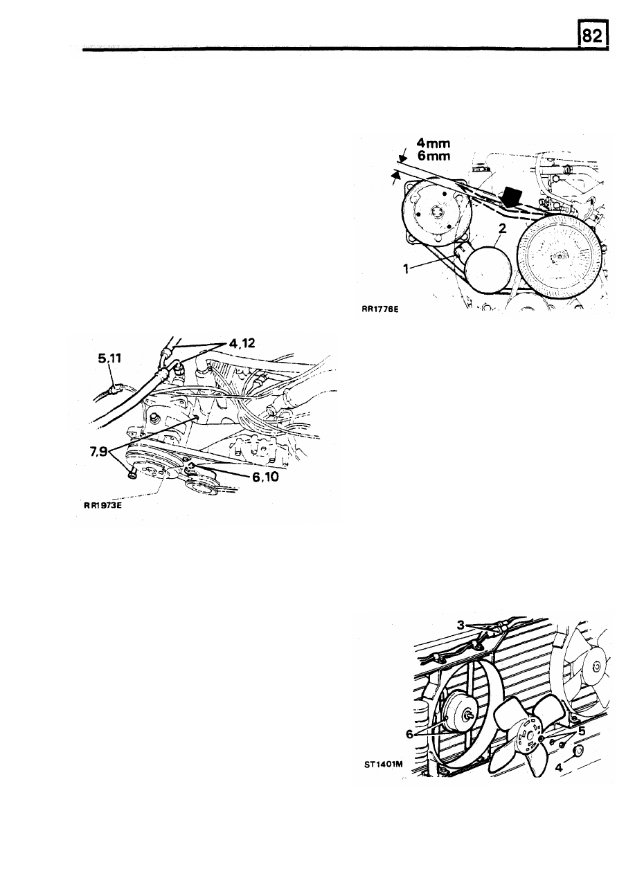
COMPRESSOR DRIVE BELT
Remove
Adjust
1.
Site vehicle in a ventilated area.
1.
Slacken idler pulley securing bolt.
2. Disconnect the battery negative lead.
3. Discharge the air conditioning system, see
Discharging system
WARNING: Wear eye and hand protection when
disconnecting
components
containing
refrigerant.
Plug
all
exposed
connections
immediately.
4. Disconnect suction and discharge unions from
compressor.
5.
Disconnect electrical lead to compressor
clutch.
6.
Slacken idler pulley and release drive belt.
7.
Remove the two compressor mounting bolts
and lift compressor clear.
2. Adjust positron of idler pulley until correct
tension
is
obtained. The belt must be tight
with 4 to 6 mm total deflection when checked
by hand midway between pulleys on the
longest run.
3.
Tighten securing bolt and recheck tension.
CONDENSER FAN MOTORS
Removal
1.
Open and secure the bonnet.
2. Release the six self tapping screws securing
the front nose and grille assembly, lift clear.
3. Disconnect the electrical leads to the fans.
4. Remove the blanking caps
from
the fan
centres.
Refit
5. Remove the 8
mm
securing nuts, star and
spring washers
from
the fan blade centres,
pull blade from its respective fan motor shaft.
6. Release the
two
fan motor retaining bolts and
remove the motor whilst feeding the fan motor
through the appropriate aperture.
8.
If
a new compressor is being fitted, drain oil
from new compressor. Drain and measure oil
from old compressor. Add 30
ml
of new oil to
this amount and refill new compressor.
9.
Locate compressor in position, fit and tighten
mounting bolts.
10. Fit compressor drive belt, see Adjustment,
Compressor drive belt
11. Connect electrical lead to compressor clutch
at the connector.
12. Evacuate air conditioning system.
See
Evacuate system.
13. Charge
air
conditioning
system.
See
Charging system.
7.
Reverse procedures
1
to
6
ensuring the fan
supply wiring is routed and securely clipped
so that the wiring does
not
foul
the fan blades
REISSUED:
FEB 1993
17
Нет комментариевНе стесняйтесь поделиться с нами вашим ценным мнением.
Текст