Defender (1993+). Manual — part 94
AIR
CONDITIONING
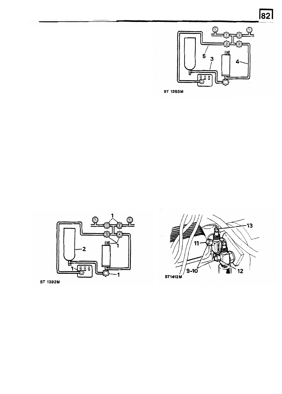
CHARGING AND TESTING EQUIPMENT
Connecting the gauge set
NOTE: 1: There are two methods
of
connecting
the charging and testing equipment, depending
on the operation to be carried out. The method
described for 'evacuating
or
charging with liquid
refrigerant' also applies to 'pressure test' and
'compressor oil level check' operations.
NOTE: 2: Various types of charge and test
equipment are available depending upon the
manufacturer chosen by the user. The equipment
illustrated may differ slightly
in
layout to that
possessed by
t
he
user,
however,
it
is
recommended that
the user adheres to the
appropriate manufacturer's instructions for the
charge and test equipment used in their
8. Put on the safety goggles.
workshop.
Fitting
1.
6.
Place the vehicle in a ventilated area away
from open flames and heat sources. Stop the
engine, open and secure the bonnet.
7.
Check that both service valves are fully open
(turned anti-clockwise).
9.
Remove the caps from the gauge connections
on the service ports.
10.
Coat the threads and flares with refrigerant
oil.
11.
Connect the low pressure charging line (blue)
from valve No.
1
to the compressor suction
service port.
12. Connect the high pressure charging line (red)
from valve No. 2 to the compressor discharge
service port.
13. Using the service wrench, turn the suction
service valve stem 'clockwise' counting the
number of turns necessary to close the valve.
Ensure that all the valves on the charging and
testing equipment are closed. Control valves
on the particular equipment selected are
numbered
1
to 4 as illustrated. The sequence
may vary on other proprietary equipment.
2. Mount a 1 1 , 3 kg drum of refrigerant upside
down on the support at the rear of the
charging equipment, and secure with the
strap.
14. After the valve is fully closed, turn the stem
out (anti-clockwise) half the number of turns
counted, this should position the valve seat in
the mid {test) position.
3.
Connect the hose from the bottom
of
the
'charging cylinder to the refrigerant drum valve.
4.
Connect the hose between the bottom
of
the
charging cylinder and the refrigerant control
valve (No. 4).
5.
Connect the hose between the vacuum pump
valve and the vacuum control valve (No.3).
REISSUED: FEB 1993
11
AIR CONDITIONING
15. Turn the stem on the discharge valve
1.
Place the vehicle in a ventilated area away
clockwise until the pressure rises on the
from open flames and heat sources.
discharge pressure gauge, If the system is to
be evacuated, the discharge service valve
3.
Open and secure the bonnet.
seat must be in the mid (test) position.
4.
Remove the caps from the compressor
connected and ready for proceeding with the
5.
Check that both compressor service valves
required operation.
are fully opened (turned anti-clockwise).
6. Close all valves on the charging and testing
7. Put on safety goggles.
17. If the engine has been operated, it must be
8.
Connect the high pressure charging line (red)
stopped prior to disconnecting the charging
from valve No. 2 to the compressor discharge
and testing equipment.
service port.
18.
Close
both
service
ports
(turn
fully
9.
Run the (blue) hose to an open tapped
anti-clockwise) until fully closed.
container of approximately one litre capacity.
19.
Close all valves
on
the charging and testing
Attach the hose to the container
so
that
it
will
equipment.
not blow out of the container. The purpose of
20. Disconnect the charging lines from the service
the container is to collect any oil carried by
ports.
the refrigerant.
21. Refit the blanking caps to the compressor
10.
Open the compressor discharge service port a
valve stems and service ports, and to the
quarter
of
a turn.
charging lines.
11. Open valve No. 2 fully.
2. Stop the engine.
16. The charging and testing equipment is now
service ports.
Removing
equipment.
22.
Close the bonnet.
12.
Slowly open the valve No. 1 one turn to allow
the refrigerant to escape, if necessary, adjust
the refrigerant flow
so
that the oil captured in
the container is not blown out of the container.
AIR CONDITIONING SYSTEM OPERATIONS
Depressurising
NOTE: The air conditioning refrigeration system
contains 'Refrigerant 12' under pressure, and
before any component
is
disconnected or
removed, the system must be discharged
of
all
pressure.
Refrigerant 12 evaporates
so
rapidly at normal
atmospheric pressures and temperatures that it
tends to freeze anything it contacts. Extreme
care must be taken t o prevent any liquid
refrigerant from contacting the
skin and
especially the eyes. Should any liquid refrigerant
get into the eyes, use a few drops of sterile
13. Measure the amount of
oil
discharged from
mineral oil t o wash them out and then wash the
the system
so
that an equal amount of new oil
eyes with
a
weak solution of boric acid. Seek
can be returned to the system during the
medical attention immediately even though the
charging operation. Discard the old
oil.
initial irritation has ceased after first aid
14.
When the gauge pressure is below 50 psi,
treatment. Always wear safety goggles when
slowly open the valve No. 1 to maintain
opening refrigerant connections.
refrigerant flow.
15.
When the pressure has been reduced, and
WARNING: Open connections slowly, keeping the
the system has been completely discharged,
hands
and
face well clear,
so
that no injury
close the valves Nos. 1 and 2 on the charging
occurs if there i s liquid i n the line. If pressure is
and testing equipment.
noticed allow it to bleed off slowly.
16. Close the compressor discharge service port
(turn anti-clockwise).
17.
Disconnect the high pressure charging line
from the compressor service port.
12
REISSUED:
FEB
1993
AIR
CONDITIONING
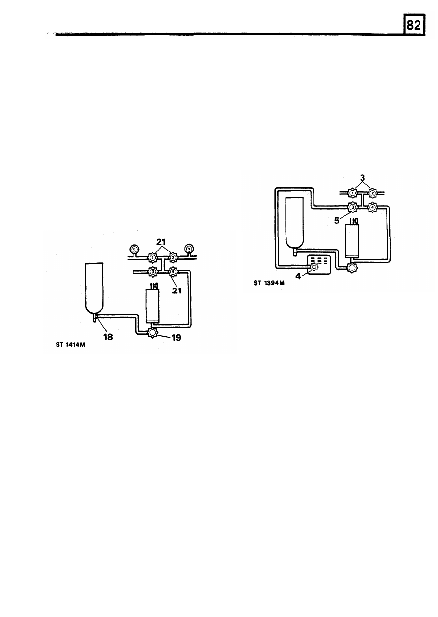
NOTE:
If it is necessary to disconnect the
1.
Depressurise the air conditioning system as
compressor hoses, the compressor should be
previously described, then connect the gauge
sealed by fully closing the relevant service valve
set as detailed under 'Charging and Testing
(turn fully clockwise). It is essential to ensure
Equipment'.
that both service valves are open before
2. Adjust both service valve seats to the mid
operating the compressor. Similarly any other
(Test) position.
component
of
the refrigeration system should be
3. Open the low and high pressure valves Nos. 1
capped immediately when disconnected.
and 2.
4.
Start the vacuum pump and check that the
vacuum pump valve is open.
5.
Slowly open the vacuum control valve No. 3.
If
the vacuum is applied to the system too
quickly, the residual oil may be drawn out.
18. Open the refrigeration drum valve.
19.
Open the valve at the base of the charging
cylinder and allow approximately 0,25 kg of
refrigerant to enter the cylinder.
20. Close the refrigeration drum valve and the
valve at the base of the charging cylinder.
21. Open the refrigerant control valve (valve
No.
4) and flush out the high and low pressure
lines by opening valves Nos. 1 and 2
momentarily until a white stream of refrigerant
is observed.
6.
In
evacuating the system it is necessary to
lower the pressure
so
that the boiling point of
water in the system is lower than the
surrounding air temperature.
At
an ambient
temperature
of
23.8°C (75°F),
it
is necessary
to lower the system pressure to 29.5 in Hg
vacuum to bring the boiling point of water to
22. Close all valves on the charging and testing
22°C (72°F). Atmospheric pressure (and
vacuum gauge readings) decrease as altitude
23.
The
air
conditioning
system
is
now
increases by approximately 25 mm Hg per
300 m. The following chart provides a guide to
the various gauge readings at differing
altitudes, for the same 10 mm Hg absolute
equipment, and fit the blanking caps.
depressurised.
Evacuating
pressure.
Whenever the system has been opened to the
Altitude, f t
m
Vacuum Reading in Hg mm
atmosphere it is necessary that the system be
0
0
29.5
750
evacuated to remove all air and moisture. It
is
also
1,000
300
28.5
725
an essential preliminary operation to charging the
2,000
600
27.4
695
system with Refrigerant 12. The evacuate operation
3,000
900
26.4
670
also provides a check for leaks due to faulty
4,000
1200
25.4
645
connections.
5,000
1500
24.5
622
6,000
1800
23.5
596
7,000
22.6
574
8,000
2400
21.8
554
9,000
2700
20.9
530
10,000
3000
20.1
510
REISSUED:
FEB
1993
13
Нет комментариевНе стесняйтесь поделиться с нами вашим ценным мнением.
Текст