Defender (1993+). Manual — part 97
AIR CONDITIONING
26.
Release the nuts and remove the bracket from
expansion valve and high pressure pipe
underneath the evaporator casing.
Place valve on bench and unscrew the high
27. Remove the wire
clip
and detach the dump
pressure pipe from the expansion valve.
valve located underneath.
46. Seal and cap all apertures; discard all ' O '
28.
Release the seven self tapping screws
rings which are renewed on assembly.
securing the outlet duct and carefully break
the sealing compound around the edge of the
duct and pull ducting plate away from
evaporator body.
47. Reverse procedures 11 to 46 noting that all
29. Remove the fifteen screws located around the
threads, unions, ' O ' rings are coated
with
cover
seam.
Remove the old sealing
refrigerant oil prior to fitting.
compound from the body and top cover.
the top of the cover.
screws adjacent to the low pressure pipe
Evaporator Matrix or Expansion Valve 6 to 10
moulding.
and then charge the air conditioning system as
32. At the side of the unit remove the two screws
previously described with Refrigerant 12.
adjacent to the air intake aperture.
33. Lift the top cover off whilst feeding the blower
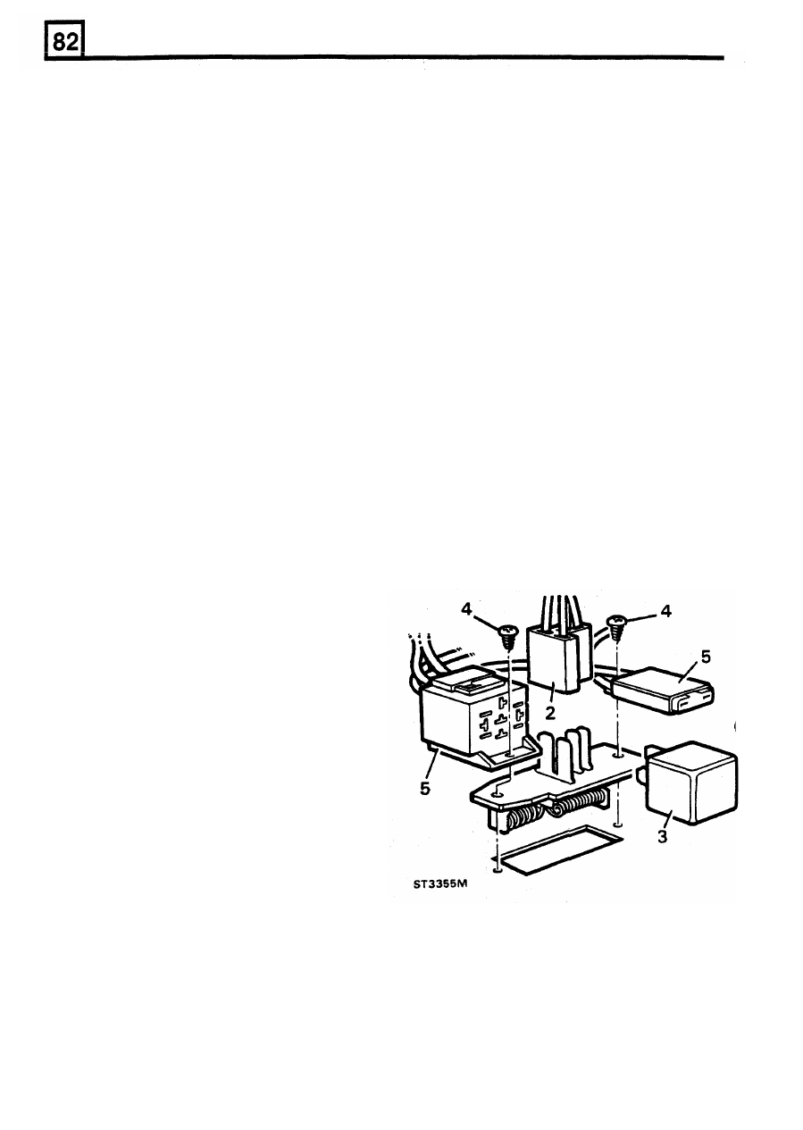
RESISTOR BLOCK
motor wiring and air control flap rod through
their respective apertures, thus exposing the
Removal
blower
motor,
heater
matrix
and
air
conditioning evaporator matrix.
1.
Disconnect the battery.
Refitting
30. Remove the four screws and four nuts from
NOTE: Depending
upon
which unit has been
31.
From the front of the unit remove the
two
Heater Matrix or Blower Motor
3
to
5
refitted reverse the appropriate procedures:
2.
Detach the electrical connector from the.
resistor block.
3. Withdraw the relay module from it's socket.
socket, fuse holder and resistor block.
Blower motor unit removal only
34.
Remove the screws retaining the motor unit to
4. Remove the screws securing relay module
the casing.
35.
Release the three bracket retaining screws
5.
Move fuse holder and relay module socket
and withdraw motor and impeller.
aside and lift resistor block clear of the
36. Detach the star washer. spring clip and
evaporator.
impeller.
37. Remove the two nuts from the motor shroud
and lift clear.
Heater/Evaporator matrices removal only
38.
Lift the support plate and insulation pad from
the matrix.
three screws adjacent to the dump valve
outlet, in addition
to
the screws next to the
heater pipes.
40. Lift the evaporator and heater matrices
together with the supporting frame containing
the air direction flap clear
of
the casing.
41. Detach the evaporator matrix by releasing the
four screws, two at
both
ends of the support
bracket.
42. Detach the heater matrix
by
removing the
self-tapping screw.
39. From the bottom
of
the casing, remove the
Refitting
Expansion valve removal
6.
To
refit the resistor block, reverse the removal
43. Support the suction pipe union with suitable
procedure.
spanners and release.
44. Remove the bleed pipe retaining nut from the
suction pipe.
45. Remove the
spring clip
retaining the
expansion valve sensor pipe to the main
suction
pipe which
now
releases the
22
REISSUED: FEB 1993
ELECTRICAL EQUIPMENT
ELECTRICAL PRECAUTIONS
Battery disconnecting
The following guidelines are intended to ensure the
Before disconnecting the battery, switch
off
all
safety of the operator whilst preventing damage to
electrical equipment.
electrical
and any electronic components fitted to the
Battery charging
Before commencing any test procedure on a vehicle
ensure that the test equipment is working correctly
Recharge the battery out of the vehicle and keep the
and any harness or connectors are in good
top well ventilated. While being charged or
condition, this particularly applies to mains leads and
discharged, and for approximately fifteen minutes
plugs.
afterwards, batteries emit hydrogen gas which is
flammable. Always ensure any battery charging area
WARNING: Before commencing work on an
is well ventilated and that every precaution is taken
ignition system, all high tension terminals,
to avoid naked flames and sparks. See SECTION 10
adaptors and diagnostic equipment for testing
for battery maintenance.
should be inspected to ensure that they are
uately insulated and shielded to prevent
GENERAL PRECAUTIONS
ental personal contacts and minimize the
of shock. Wearers of surgically implanted
Switch-off ignition prior to making any connection or
maker devices should not be in close
disconnection in the system as electrical surge
proximity to ignition circuits or diagnostic
caused by disconnecting 'live' connections can
equipment.
damage electronic components.
Polarity
Never reverse connect the vehicle battery and
can cause tracking or high-resistance contacts.
always observe the correct polarity when connecting
test equipment.
High voltage circuits
Whenever disconnecting live high tension circuits
always use insulated pliers and never allow the open
end of a high tension lead to come into contact with
other components particularly electronic control units.
Exercise caution when measuring the voltage on the
coil terminals while the engine is running, since, high
voltage spikes can occur on these terminals.
Connectors and harness
Always ensure that these items are dry and oil free
before disconnecting and connecting test equipment.
Never force connectors apart either by using tools or
by pulling on the wiring harness. Always ensure
locking tabs are disengaged before removal and note
orientation to enable correct reconnection. Ensure
that any protective covers and substances are
replaced if disturbed. Having confirmed a component
to be faulty switch-off the ignition and disconnect the
battery. Remove the component and support the
disconnected
harness.
When
replacing
the
component keep oily hands away from electrical
connection areas and push connectors home until
any locking tabs fully engage.
Ensure hands and work surfaces are clean and free
of grease, swarf, etc. as grease collects dirt which
When handling printed circuit boards, treat them as
you would a hi-fi record
-
hold by the edges only.
Prior to commencing a test, and periodically during a
test, touch a good earth, for instance, a cigar lighter
socket, to discharge body static as some electronic
components are vulnerable to static electricity.
REISSUED: FEB 1993
1
vehicle.
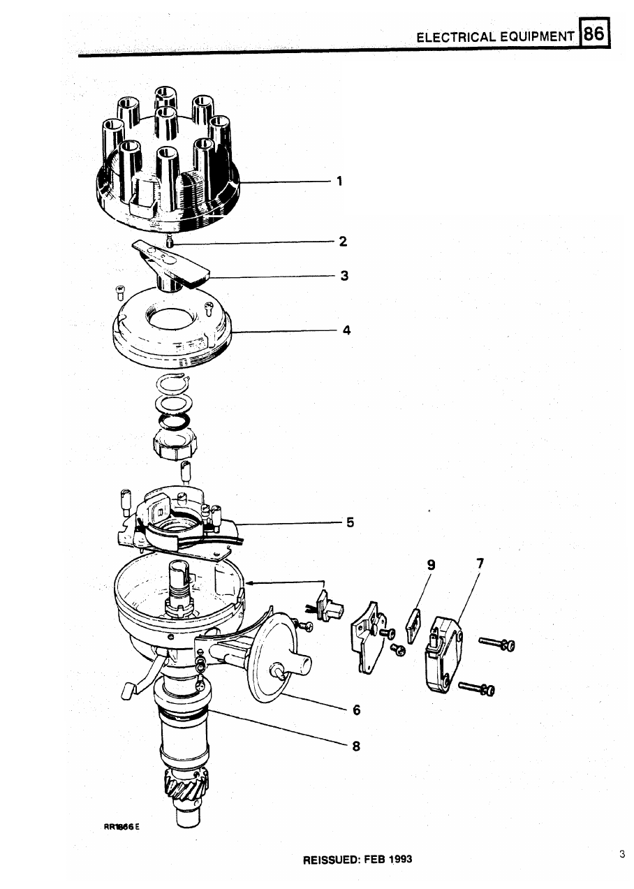
ELECTRICAL EQUIPMENT
DISTRIBUTOR - 35DLM8
NOTE: Marking distributor enables refitting in
exact original position, but if engine is turned
The Lucas 35DLM8 distributor has
a
conventional
while distributor is removed, complete ignition
advance/retard unit
and
centrifugal automatic
timing procedure must be followed.
advance mechanism.
A
pick-up module, in conjunction with a rotating
7. Release the distributor clamp and remove the
timing reluctor inside the distributor body, generates
timing signals. These are applied to an electronic
ignition amplifier module mounted on the side of the
Refitting
distributor body.
NOTE: I f a new distributor is being fitted, mark
NOTE: The pick-up air gap is factory set.
Do
not
body in same relative position as distributor
adjust the gap unless the pick-up is being
removed.
changed or the base plate has been moved. Use
a
non-ferrous feeler gauge
to
set the air gap.
Remove and refit
Removing
distributor.
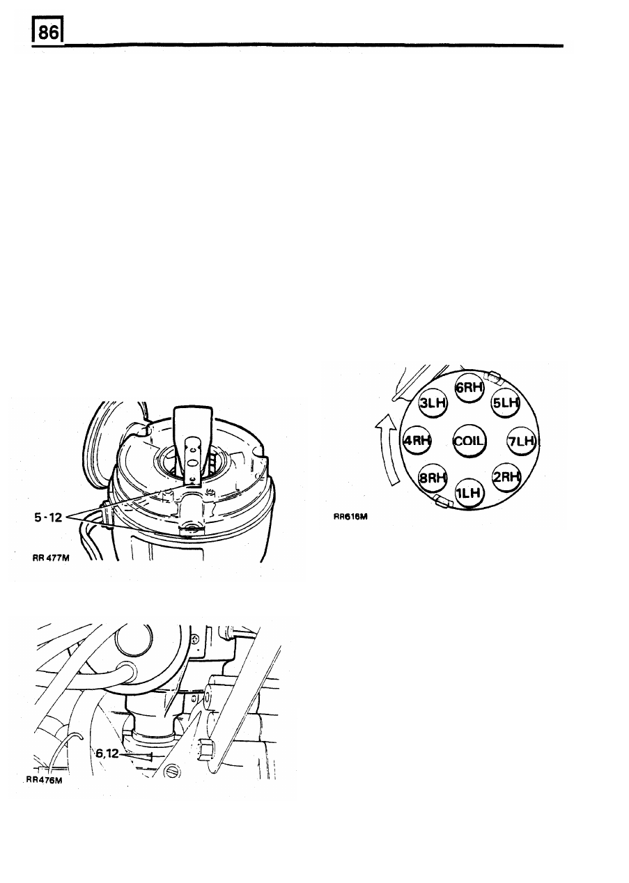
8. Leads for distributor cap should be connected
as illustrated.
Figures
1
to
8 inclusive indicate plug lead numbers.
RH
-
Right-hand side
of
engine, when viewed
1.
Disconnect battery.
from the rear.
2.
Disconnect vacuum pipe(s).
LH
-
Left-hand side
of
engine, when viewed
3.
Remove distributor cap.
from the rear.
4.
Disconnect low tension lead from coil.
5.
Mark distributor body in relation
to
centre line
of rotor arm.
9. If engine has not been turned whilst distributor
has been removed, proceed as follows (items
10 to 17).
10.
Fit new ' O ' ring seal to distributor housing.
11. Turn distributor drive until centre line of rotor
arm is 30° anti-clockwise from mark made on
top edge
of
distributor body.
12. Fit distributor in accordance with alignment
markings.
6.
Add alignment marks to distributor and front
cover.
NOTE: It may be necessary t o align oil pump
drive shaft t o enable distributor drive shaft t o
engage i n slot.
13. Fit clamp and bolt. Secure distributor in exact
orginal position.
14. Connect vacuum pipe to distributor and low
tension lead to coil.
15. Fit distributor cap.
16.
Reconnect battery.
17. Using suitable electronic equipment, set the
ignition timing,
See
IGNITION TIMING
ADJUSTMENT
2
REISSUED: FEB 1993
Нет комментариевНе стесняйтесь поделиться с нами вашим ценным мнением.
Текст