Toyota Sequoia (2005). Manual — part 585
I28593
(Shielded)
(Shielded)
R22
5
6
3
4
2
5
17
16
19
18
20
R22
R22
R22
IF4
ID2
R22
L+
SGND
W
W
W
W
6
IF4
3
IF4
4
IF4
2
IF4
ID2
ID2
ID2
ID2
(Shielded)
R25
Television Display Assy
Multi–display
Controller Sub–assy
L–
R+
R–
HPL+
SLD1
HPL–
HPR+
HPR–
W
W
W
W
W
W
W
W
5
6
3
4
2
–
DIAGNOSTICS
REAR SEAT ENTERTAINMANT SYSTEM
DI–2135
2329
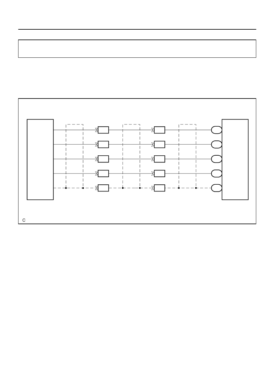
Sound signal circuit (Multi–display controller sub–assy – Televi-
sion display assy)
CIRCUIT DESCRIPTION
This is the sound signal circuit from the television display assy to the multi–display controller sub–assy.
WIRING DIAGRAM
DIDBH–01
I28332
Television Display Assy:
Multi–display Controller Sub–assy:
HPL–
HPL+
HPR+
HPR–
SLD1
SGND
R+
R–
L+
L–
R22
R25
DI–2136
–
DIAGNOSTICS
REAR SEAT ENTERTAINMANT SYSTEM
2330
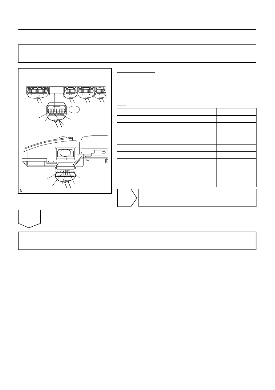
INSPECTION PROCEDURE
1
Check harness and connector (Multi–display controller sub–assy – Television
display assy).
PREPARATION:
Disconnect the R22 and R25 connectors.
CHECK:
Measure the resistance according to the value(s) in the table
below.
OK:
Symbol (Tester connection)
Condition
Specified condition
HPR+ (R22–19) – R+ (R25–3)
Always
Below 1
Ω
HPR– (R22–18) – R– (R25–4)
Always
Below 1
Ω
HPL+ (R22–17) – L+ (R25–5)
Always
Below 1
Ω
HPL– (R22–16) – L– (R25–6)
Always
Below 1
Ω
SLD1 (R22–20) – SGND (R25–2)
Always
Below 1
Ω
HPR+ (R22–19) – Body ground
Always
10 k
Ω
or higher
HPR– (R22–18) – Body ground
Always
10 k
Ω
or higher
HPL+ (R22–17) – Body ground
Always
10 k
Ω
or higher
HPL– (R22–16) – Body ground
Always
10 k
Ω
or higher
SLD1 (R22–20) – Body ground
Always
10 k
Ω
or higher
NG
Repair or replace harness or connector.
OK
Proceed to next circuit inspection shown in problem symptoms table (See page
I28669
AR+
AR–
AL+
AL–
SG4
(Shielded)
R22
6
7
8
9
5
5
4
3
2
6
R22
R22
R22
R22
R+
R–
L+
L–
SLD
W
W
W
W
D23
Disc Player Controller
Multi–display
Controller Sub–assy
–
DIAGNOSTICS
REAR SEAT ENTERTAINMANT SYSTEM
DI–2137
2331
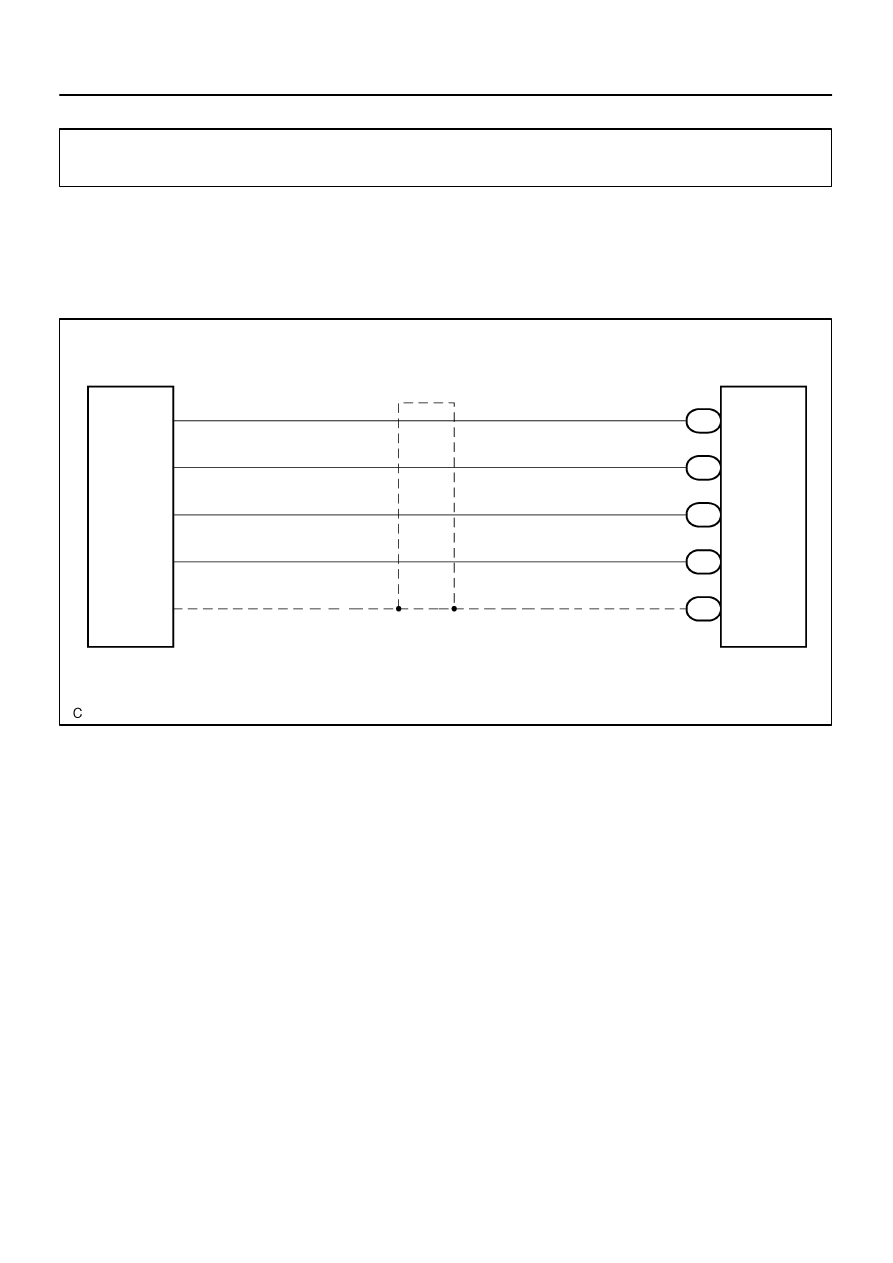
Sound signal circuit (Multi–display controller sub–assy – Disc
player controller)
CIRCUIT DESCRIPTION
This is the sound signal circuit from the disc player controller to the multi–display controller sub–assy.
WIRING DIAGRAM
DIDBI–01
I28330
Disc Player Controller:
Multi–display Controller Sub–assy:
R+
L+
R–
L–
SLD
AL+
AR+
AR–
SG4
AL–
D23
R22
DI–2138
–
DIAGNOSTICS
REAR SEAT ENTERTAINMANT SYSTEM
2332
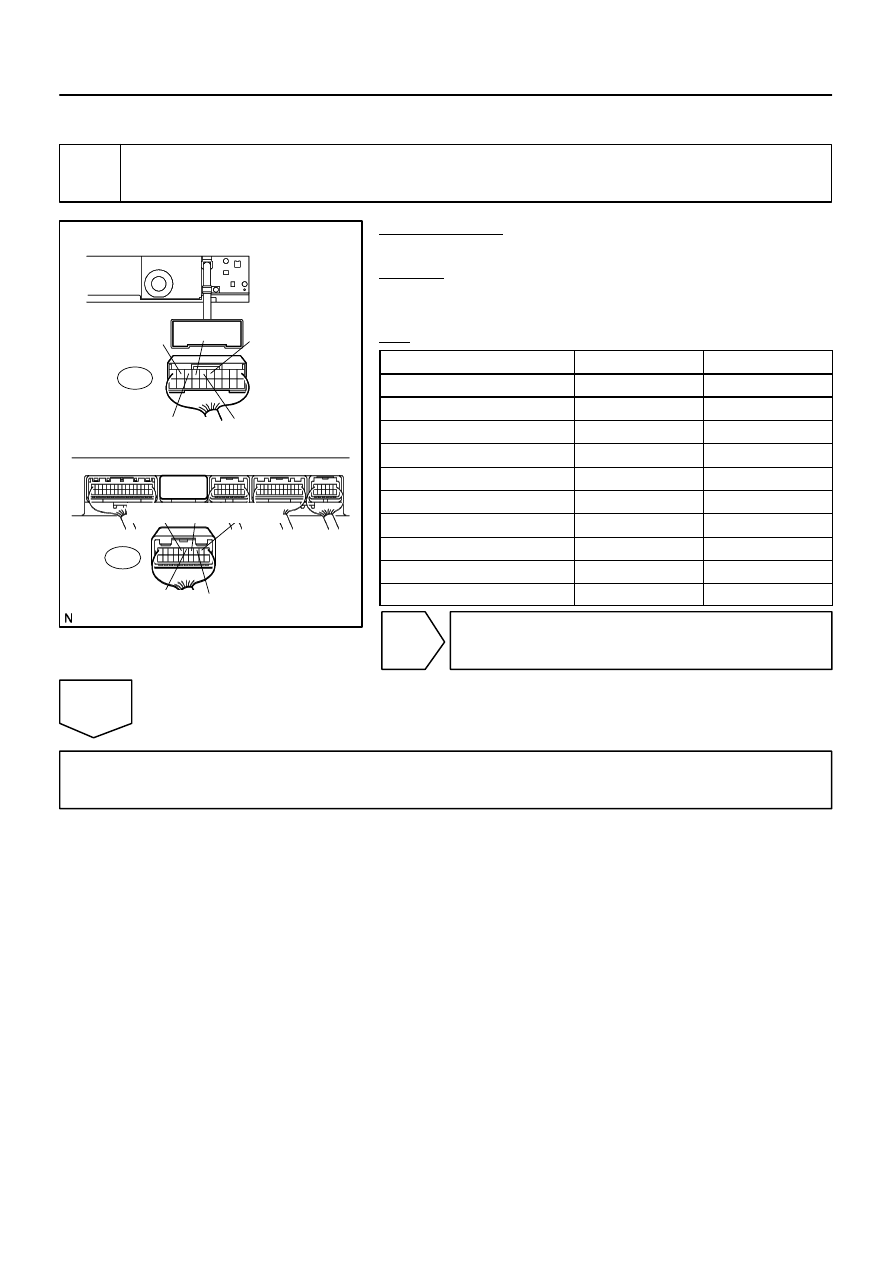
INSPECTION PROCEDURE
1
Check harness and connector (Multi–display controller sub–assy – Disc player
controller).
PREPARATION:
Disconnect the R22 and D23 connectors.
CHECK:
Measure the resistance according to the value(s) in the table
below.
OK:
Symbol (Tester connection)
Condition
Specified condition
L– (D23–9) – AL– (R22–2)
Always
Below 1
Ω
L+ (D23–8) – AL+ (R22–3)
Always
Below 1
Ω
R– (D23–7) – AR– (R22–4)
Always
Below 1
Ω
R+ (D23–6) – AR+ (R22–5)
Always
Below 1
Ω
SLD (D23–5) – SG4 (R22–6)
Always
Below 1
Ω
L– (D23–9) – Body ground
Always
10 k
Ω
or higher
L+ (D23–8) – Body ground
Always
10 k
Ω
or higher
R– (D23–7) – Body ground
Always
10 k
Ω
or higher
R+ (D23–6) – Body ground
Always
10 k
Ω
or higher
SLD (D23–5) – Body ground
Always
10 k
Ω
or higher
NG
Repair or replace harness or connector.
OK
Proceed to next circuit inspection shown in problem symptoms table (See page
Нет комментариевНе стесняйтесь поделиться с нами вашим ценным мнением.
Текст