Toyota Sequoia (2005). Manual — part 584
I28666
Multi–display
Controller Sub–assy
R21
12
R21
11
R21
10
BR
BR
AUXR
AUXL
SG6
1
2
3
(Shielded)
V10
VTR Terminal
AUXR
AUXL
SG7
–
DIAGNOSTICS
REAR SEAT ENTERTAINMANT SYSTEM
DI–2131
2325
Sound signal circuit (Multi–display controller sub–assy – VTR ter-
minal)
CIRCUIT DESCRIPTION
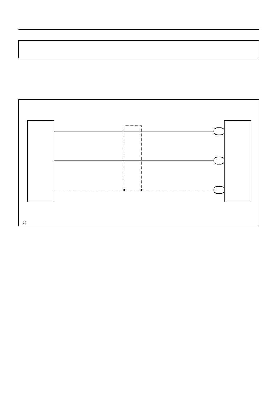
This is the sound signal circuit from the VTR terminal to the multi–display controller sub–assy.
WIRING DIAGRAM
DIDBF–01
I28321
I28327
VTR Terminal:
Multi–display Controller Sub–assy:
SG6
V10
R21
AUXL
AUXR
AUXR
AUXL
SG7
DI–2132
–
DIAGNOSTICS
REAR SEAT ENTERTAINMANT SYSTEM
2326
INSPECTION PROCEDURE
1
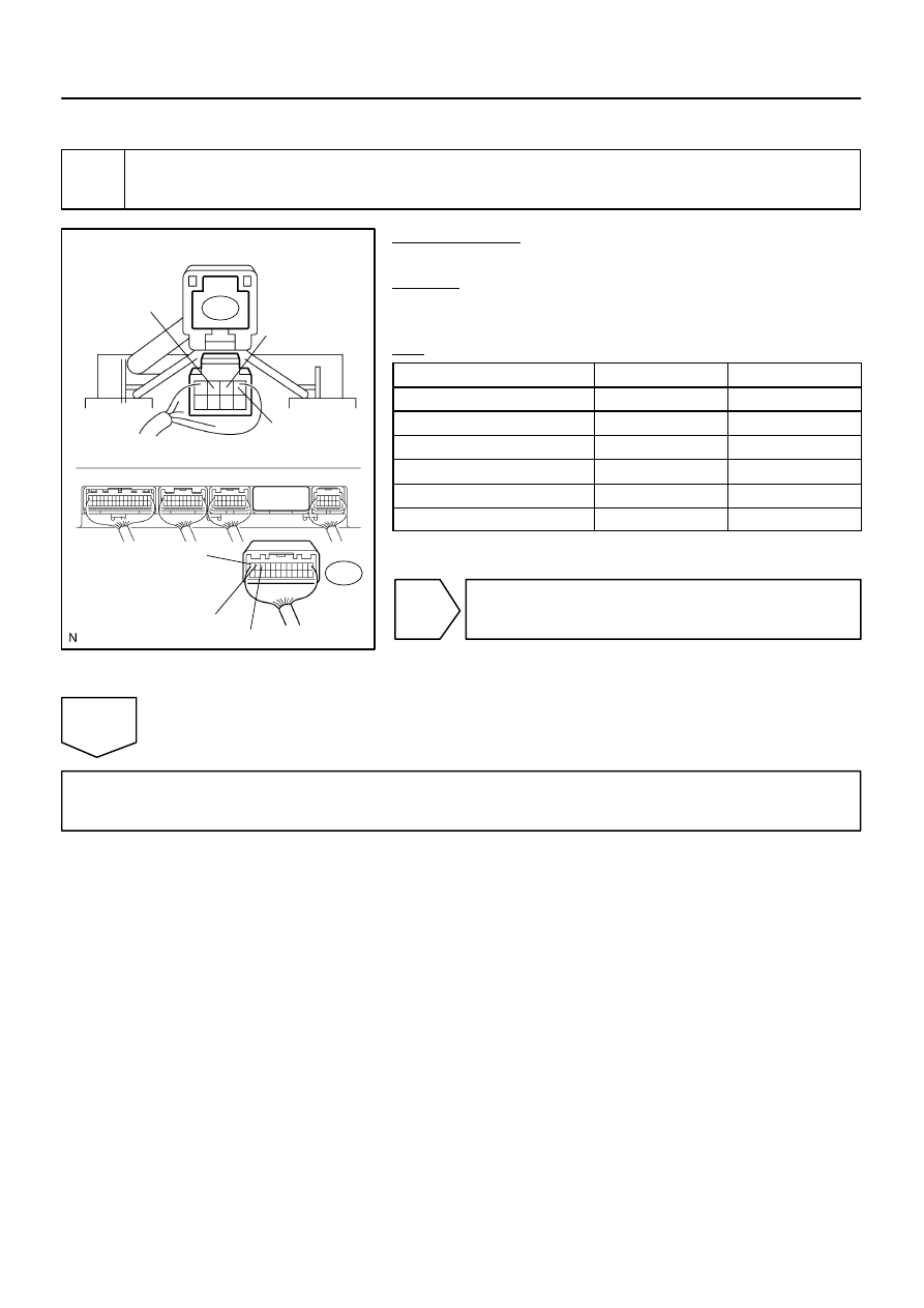
Check harness and connector (VTR terminal – Multi–display controller sub–
assy).
PREPARATION:
Disconnect the R21 and V10 connectors.
CHECK:
Measure the resistance according to the value(s) in the table
below.
OK:
Symbol (Tester connection)
Condition
Specified condition
SG6 (V10–3) – SG7 (R21–10)
Always
Below 1
Ω
AUXR (V10–1) – AUXR (R21–12)
Always
Below 1
Ω
AUXL (V10–2) – AUXL (R21–11)
Always
Below 1
Ω
AUXR (V10–1) – Body ground
Always
10 k
Ω
or higher
AUXL (V10–2) – Body ground
Always
10 k
Ω
or higher
SG6 (V10–3) – Body ground
Always
10 k
Ω
or higher
NG
Repair or replace harness or connector.
OK
Proceed to next circuit inspection shown in problem symptoms table (See page
I28668
HP1R
HP1L
SG5
R21
9
R21
8
R21
7
BR
BR
HPR
HPL
SGND
1
2
3
(Shielded)
H10
Headphone Terminal LH
Multi–display
Controller Sub–assy
HP2R
HP2L
SG6
R21
21
R21
20
R21
19
BR
BR
HPR
HPL
SGND
1
2
3
(Shielded)
H11
Headphone Terminal RH
–
DIAGNOSTICS
REAR SEAT ENTERTAINMANT SYSTEM
DI–2133
2327
Sound signal circuit (Multi–display controller sub–assy – Head-
phone terminal)
CIRCUIT DESCRIPTION
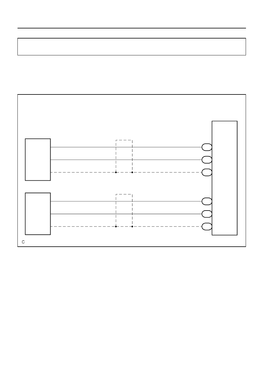
This is the sound signal circuit from the headphone terminal to the multi–display controller sub–assy.
WIRING DIAGRAM
DIDBG–01
I28333
Headphone Terminal:
Multi–display Controller Sub–assy:
SG5
HP1L
HP1R
SG6
HP2L
HP2R
R21
H10
H11
HPR
HPL
SGND
DI–2134
–
DIAGNOSTICS
REAR SEAT ENTERTAINMANT SYSTEM
2328
INSPECTION PROCEDURE
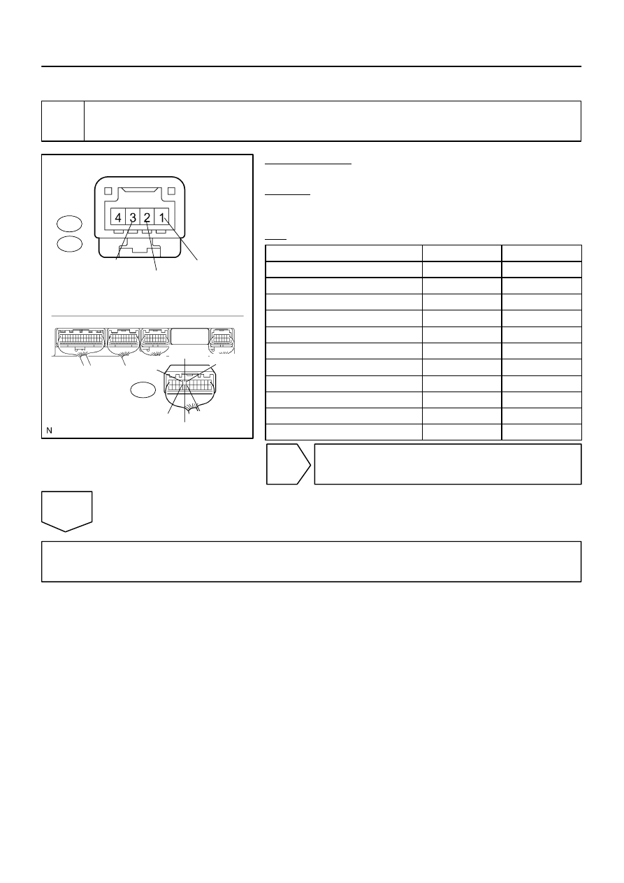
1
Check harness and connector (Headphone terminal – Multi–display controller
sub–assy).
PREPARATION:
Disconnect the H10 (H11) and R21 connectors.
CHECK:
Measure the resistance according to the value(s) in the table
below.
OK:
Symbol (Tester connection)
Condition
Specified condition
HPR (H10–1) – HP1R (R21–9)
Always
Below 1
Ω
HPL (H10–2) – HP1L (R21–8)
Always
Below 1
Ω
HPR (H11–1) – HP2R (R21–21)
Always
Below 1
Ω
HPL (H11–2) – HP2L (R21–20)
Always
Below 1
Ω
SGND (H10–3) – SG5 (R21–7)
Always
Below 1
Ω
SGND (H11–3) – SG6 (R21–19)
Always
Below 1
Ω
HPR (H10–1, H11–1) – Body ground
Always
10 k
Ω
or higher
HPL (H10–2, H11–2) – Body ground
Always
10 k
Ω
or higher
SGND (H10–3, H11–3) – Body ground
Always
10 k
Ω
or higher
SGND (H10–3) – Body ground
Always
10 k
Ω
or higher
SGND (H11–3) – Body ground
Always
10 k
Ω
or higher
NG
Repair or replace harness or connector.
OK
Proceed to next circuit inspection shown in problem symptoms table (See page
Нет комментариевНе стесняйтесь поделиться с нами вашим ценным мнением.
Текст