Toyota Sequoia (2005). Manual — part 586
I28592
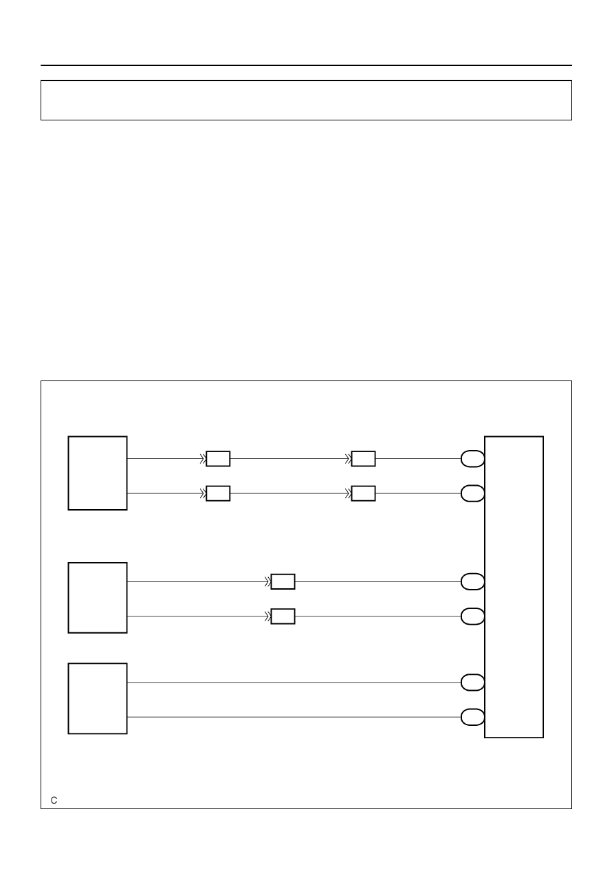
Multi–display
Controller Sub–assy
R25
Television Display Assy
IF4
9
LG
5
TX2+
ID2
17
R21
LG
LG
IF4
10
LG
4
TX2–
ID2
18
R21
LG
LG
TX+
TX–
LG
31
TX+
IF3
14
R23
L
LG
30
TX–
IF3
15
R23
LG
TX+ (*1)
9
10
9
10
R27 (*1)
Radio and Navigation Assy
R19 (*2)
Radio Receiver Assy
D23
Disc Player Controller
13
TX3–
R22
LG
14
TX3+
R22
TX–
TX+
18
17
LG
*1: w/ Navigation System
*2: w/o Navigation System
TX1+ (*2)
TX– (*1)
TX1– (*2)
–
DIAGNOSTICS
REAR SEAT ENTERTAINMANT SYSTEM
DI–2139
2333
AVC–LAN circuit
CIRCUIT DESCRIPTION
Each unit of this system connected to the AVC–LAN (communication bus) transfers the signal of each switch
by communication.
When a short to +B or short to ground occurs in this AVC– LAN, this system will not function normally as
communication is discontinued.
This system has 2 kinds of AVC–LAN: main AVC–LAN and sub AVC–LAN.
w/ navigation system:
In the main AVC–LAN, the radio and navigation assy becomes the communication master and has enough
resistance necessary for communication.
w/o navigation system:
In the main AVC–LAN, the radio receiver assy becomes the communication master and has enough resis-
tance necessary for communication.
In the sub AVC–LAN, the multi–display controller sub–assy becomes the communication master and has
enough resistance necessary for communication.
WIRING DIAGRAM
DIDBJ–01
DI–2140
–
DIAGNOSTICS
REAR SEAT ENTERTAINMANT SYSTEM
2334
INSPECTION PROCEDURE
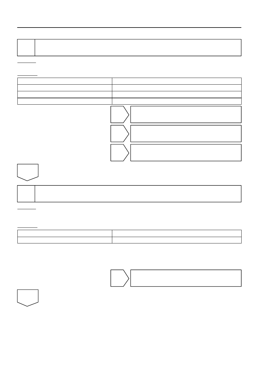
1
Inspect apparatus.
CHECK:
Choose the apparatus to be inspected.
RESULT:
Television display assy
Go to step A
Radio and navigation assy (w/ Navigation System)
Go to step B
Radio receiver assy (w/o Navigation System)
Go to step C
Disc player controller
Go to step D
B
Go to step 4.
C
Go to step 6.
D
Go to step 7.
A
2
Service check mode (Television display assy).
CHECK:
Perform the service check (See page
).
Start the diagnosis system and read the check result for the television display assy.
RESULT:
”NCON” is displayed or result is not displayed (Rr–TV)
Go to step A
”GOOD” is displayed
Go to step B
HINT:
This system has 2 kinds of AVC–LAN: main AVC–LAN and sub AVC–LAN. The television display is
connected for the sub AVC–LAN.
Perform the communication check for the diagnosis system (See page
B
Replace multi–display controller sub–assy.
A
I28616
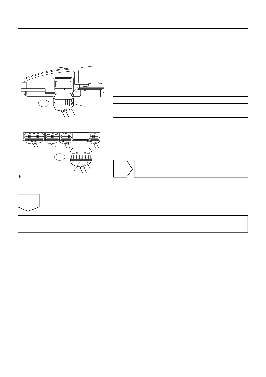
Television Display Assy:
TX+
TX–
Multi display Controller Sub–assy:
TX2+
TX2–
R25
R21
–
DIAGNOSTICS
REAR SEAT ENTERTAINMANT SYSTEM
DI–2141
2335
3
Check harness and connector (Television display assy – Multi–display controller
sub–assy).
PREPARATION:
Disconnect the R21 and R25 connectors.
CHECK:
Measure the resistance according to the value(s) in the table
below.
OK:
Symbol (Tester connection)
Condition
Specified condition
TX+ (R25–9) – TX2+ (R21–5)
Always
Below 1
Ω
TX– (R25–10) – TX2– (R21–4)
Always
Below 1
Ω
TX+(R25–9) – Body ground
Always
10 k
Ω
or higher
TX– (R25–10) – Body ground
Always
10 k
Ω
or higher
NG
Repair or replace harness or connector.
OK
Replace television display assy.
DI–2142
–
DIAGNOSTICS
REAR SEAT ENTERTAINMANT SYSTEM
2336
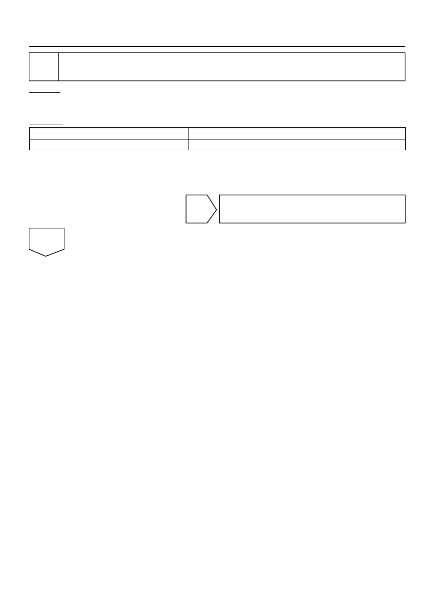
4
Service check mode (Multi–display controller sub–assy).
CHECK:
Perform the service check (See page
).
Start the diagnosis system and read the check result for the radio and navigation assy.
RESULT:
”NCON” is displayed or result is not displayed (RSE ECU)
Go to step A
”GOOD” is displayed
Go to step B
HINT:
This system has 2 kinds of AVC–LAN: main AVC–LAN and sub AVC–LAN. The television display is
connected for the sub AVC–LAN.
Perform the communication check for the diagnosis system (See page
B
Replace radio and navigation assy.
A
Нет комментариевНе стесняйтесь поделиться с нами вашим ценным мнением.
Текст