Toyota Sequoia (2005). Manual — part 583
I28597
IF3
R–L+
R–R–
R–R+
R–L–
W
(Shielded)
Multi–display
Controller Sub–assy
R23
26
R23
25
R23
24
R23
23
R23
27
W
W
W
IF3
IF3
IF3
IF3
(Shielded)
RSL+
RSR–
RSR+
RSL–
R19
15
R19
16
R19
17
R19
18
R19
14
SLD1
SG2
Radio Receiver Assy
W
G
B
R
18
19
20
21
17
–
DIAGNOSTICS
REAR SEAT ENTERTAINMANT SYSTEM
DI–2127
2321
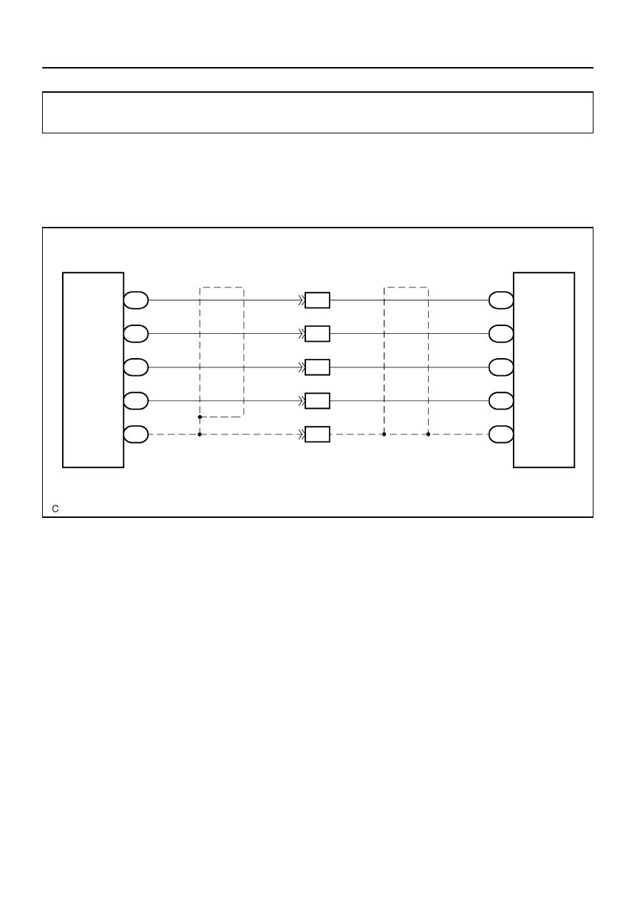
Sound signal circuit (From radio receiver assy to multi–display
sub–assy)
CIRCUIT DESCRIPTION
This is the sound signal circuit from the radio receiver assy to the multi–display controller sub–assy.
WIRING DIAGRAM
DIDBD–01
I28618
Multi–display Controller Sub–assy:
R–L–
R–L+
R–R–
R–R+
Radio Receiver Assy:
SG2
RSR+ RSL+
RSR–
RSL–
SLD1
R19
R23
DI–2128
–
DIAGNOSTICS
REAR SEAT ENTERTAINMANT SYSTEM
2322
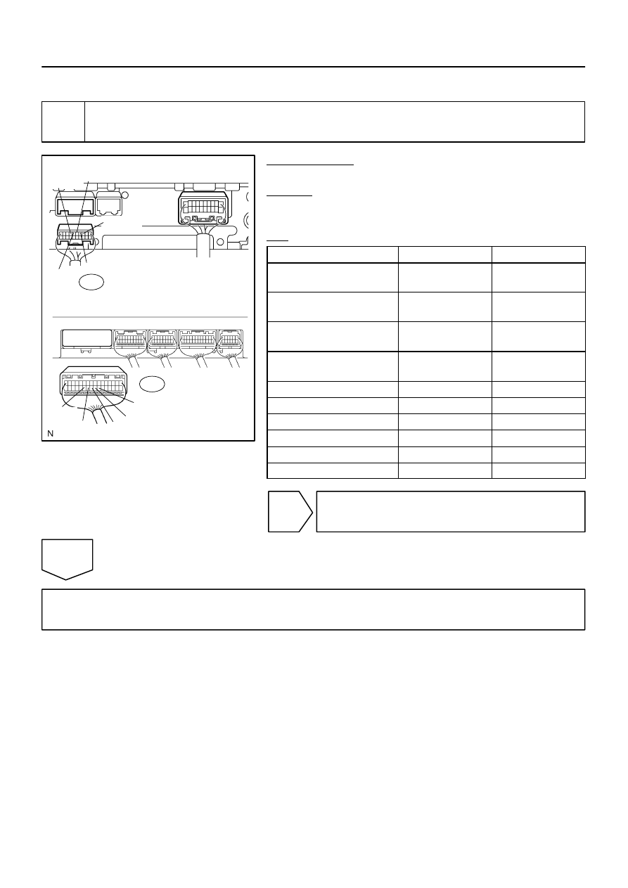
INSPECTION PROCEDURE
1
Check harness and connector (Radio receiver assy – Multi–display controller
sub–assy).
PREPARATION:
Disconnect the R23 and R19 connectors.
CHECK:
Measure the resistance according to the value(s) in the table
below.
OK:
Symbol (Tester connection)
Condition
Specified condition
RSR+ (R19–15) –
R–R+ (R23–26)
Always
Below 1
Ω
RSR– (R19–16) –
R–R– (R23–25)
Always
Below 1
Ω
RSL+ (R19–17) –
R–L+ (R23–24)
Always
Below 1
Ω
RSL– (R19–18) –
R–L– (R23–23)
Always
Below 1
Ω
SLD1 (R19–14) – SG2 (R23–27)
Always
Below 1
Ω
RSR+ (R19–15) – Body ground
Always
10 k
Ω
or higher
RSR– (R19–16) – Body ground
Always
10 k
Ω
or higher
RSL+ (R19–17) – Body ground
Always
10 k
Ω
or higher
RSL– (R19–18) – Body ground
Always
10 k
Ω
or higher
SLD1 (R19–14) – Body ground
Always
10 k
Ω
or higher
NG
Repair or replace harness or connector.
OK
Proceed to next circuit inspection shown in problem symptoms table (See page

I28597
IF3
R–L+
R–R–
R–R+
R–L–
W
(Shielded)
Multi–display
Controller Sub–assy
R23
26
R23
25
R23
24
R23
23
R23
27
W
W
W
IF3
IF3
IF3
IF3
(Shielded)
R–L+
R–R–
R–R+
R–L–
R27
15
R27
16
R27
17
R27
18
R27
14
RSLD
SG2
Radio and Navigation Assy
W
G
B
R
18
19
20
21
17
–
DIAGNOSTICS
REAR SEAT ENTERTAINMANT SYSTEM
DI–2129
2323
Sound signal circuit (From radio and navigation assy to multi–
display sub–assy)
CIRCUIT DESCRIPTION
This is the sound signal circuit from the radio and navigation assy to the multi–display controller sub–assy.
WIRING DIAGRAM
DIDBE–01
I28750
Radio and Navigation Assy:
R27
RSLD
R–R+
R–R–
R–L+
R–L–
I28614
SG2
R23
Multi–display Controller Sub–assy:
R–R+
R–R–
R–L+
R–L–
DI–2130
–
DIAGNOSTICS
REAR SEAT ENTERTAINMANT SYSTEM
2324
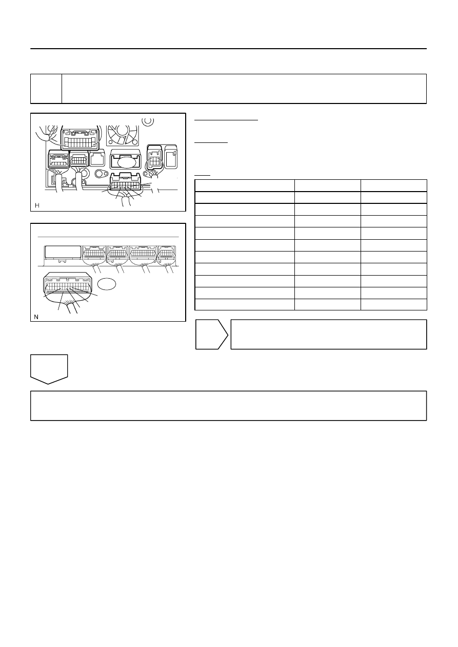
INSPECTION PROCEDURE
1
Check harness and connector (Radio and navigation assy – Multi–display con-
troller sub–assy).
PREPARATION:
Disconnect the R23 and R27 connectors.
CHECK:
Measure the resistance according to the value(s) in the table
below.
OK:
Symbol (Tester connection)
Condition
Specified condition
R–R+ (R27–15) – R–R+ (R23–26)
Always
Below 1
Ω
R–R– (R27–16) – R–R– (R23–25)
Always
Below 1
Ω
R–L+ (R27–17) – R–L+ (R23–24)
Always
Below 1
Ω
R–L– (R27–18) – R–L– (R23–23)
Always
Below 1
Ω
RSLD (R27–14) – SG2 (R23–27)
Always
Below 1
Ω
R–R+ (R27–15) – Body ground
Always
10 k
Ω
or higher
R–R– (R27–16) – Body ground
Always
10 k
Ω
or higher
R–L+ (R27–17) – Body ground
Always
10 k
Ω
or higher
R–L– (R27–18) – Body ground
Always
10 k
Ω
or higher
RSLD (R27–14) – Body ground
Always
10 k
Ω
or higher
NG
Repair or replace harness or connector.
OK
Proceed to next circuit inspection shown in problem symptoms table (See page
Нет комментариевНе стесняйтесь поделиться с нами вашим ценным мнением.
Текст