Nissan Qashqai (2007-2010). Manual — part 927

HAC-68
< COMPONENT DIAGNOSIS >
[AUTOMATIC AIR CONDITIONER]
MAGNET CLUTCH
Is the inspection result normal?
YES
>> GO TO 10.
NO
>> Replace BCM. Refer to
10.
CHECK COMPRESSOR ON SIGNAL
1.
Turn ignition switch OFF.
2.
Connect auto amp. harness connector.
3.
Turn ignition switch ON.
4.
Check voltage between auto amp. harness connector M53 terminal 5 and ground.
Is the inspection result normal?
YES
>> GO TO 11.
NO
>> Replace auto amp.
11.
CHECK REFRIGERANT PRESSURE SENSOR
WITH CONSULT-III
1.
Start the engine.
2.
Check voltage of refrigerant pressure sensor in “DATA MONITOR”. Refer to
HAC-92, "MR20DE : Reference Value"
(K9K).
WITHOUT CONSULT-III
1.
Start the engine.
2.
Check voltage between ECM harness connector F8 terminal 41 (With Gasoline Engine) or F68 terminal
78 (With Diesel Engine) and ground.
With Gasoline Engine
With Diesel Engine
Is the inspection result normal?
YES
>> •
WITH CONSULT-III: GO TO 12.
•
WITHOUT CONSULT-III: GO TO 13.
NO
>> Refer to
[HR16DE (WITH EURO-OBD)],
[MR20DE (WITH
EC-1215, "Diagnosis Procedure"
[MR20DE (WITHOUT EURO-OBD)], or
(K9K).
BCM
—
Voltage
Connector
Terminal
M65
14
Ground
Battery voltage
(+)
(
−
)
Condition
Voltage
Auto amp.
—
Connector
Terminal
M53
5
Ground
A/C switch: ON
(Blower motor operates.)
Approx. 0
(+)
(
−
)
Condition
Voltage
ECM
—
Connector
Terminal
F8
41
Ground
A/C switch: ON
(Blower motor operates.)
Approx. 1.0 - 4.0
(+)
(
−
)
Condition
Voltage
ECM
—
Connector
Terminal
F68
78
Ground
A/C switch: ON
(Blower motor operates.)
Approx. 2.3

MAGNET CLUTCH
HAC-69
< COMPONENT DIAGNOSIS >
[AUTOMATIC AIR CONDITIONER]
C
D
E
F
G
H
J
K
L
M
A
B
HAC
N
O
P
12.
CHECK BCM INPUT (FAN ON) SIGNAL
Check FAN ON/OFF signal in “DATA MONITOR”. Refer to
HAC-31, "CONSULT-III Function"
.
Is the inspection result normal?
YES
>> GO TO 16.
NO
>> GO TO 13.
13.
CHECK CIRCUIT CONTINUITY BETWEEN BCM AND AUTO AMP.
1.
Turn ignition switch OFF.
2.
Disconnect BCM connector and auto amp. connector.
3.
Check continuity between BCM harness connector M65 terminal 15 and auto amp. harness connector
M53 terminal 24.
Is the inspection result normal?
YES
>> GO TO 14.
NO
>> Repair harness or connector.
14.
CHECK BCM
1.
Connect BCM harness connector.
2.
Turn ignition switch ON.
3.
Check voltage between BCM harness connector M65 terminal 15 and ground.
Is the inspection result normal?
YES
>> GO TO 15.
NO
>> Replace BCM. Refer to
.
15.
CHECK FAN ON SIGNAL
1.
Turn ignition switch OFF.
2.
Connect auto amp. connector.
3.
Turn ignition switch ON.
4.
Check voltage between auto amp. harness connector M53 terminal 24 and ground.
Is the inspection result normal?
YES
>> GO TO 16.
NO
>> Replace auto amp.
16.
CHECK CAN COMMUNICATION
Check CAN communication. Refer to
LAN-59, "CAN Communication Signal Chart"
• ECM – IPDM E/R
• ECM – BCM
Is the inspection result normal?
FAN CONTROL DIAL ON
: FAN ON SIG ON
FAN CONTROL DIAL OFF
: FAN ON SIG OFF
BCM
Auto amp.
Continuity
Connector
Terminal
Connector
Terminal
M65
15
M53
24
Continuity should exist
BCM
—
Voltage
Connector
Terminal
M65
15
Ground
Battery voltage
(+)
(
−
)
Condition
Voltage
Auto amp.
—
Connector
Terminal
M53
24
Ground
Fan control dial: ON
Approx. 0
HAC-70
< COMPONENT DIAGNOSIS >
[AUTOMATIC AIR CONDITIONER]
MAGNET CLUTCH
YES
>> Replace ECM.
NO
>> Repair or replace malfunctioning part(s).
Component Inspection
INFOID:0000000000954659
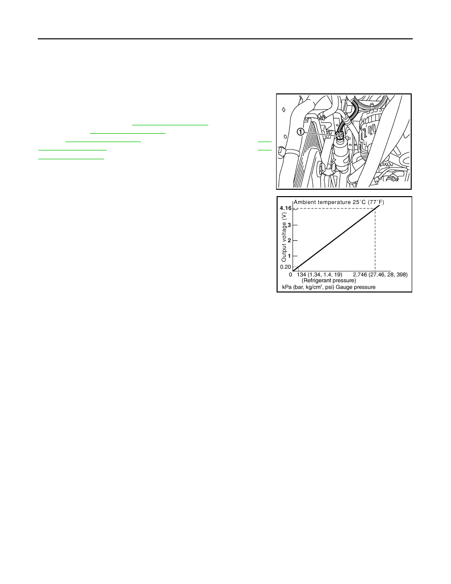
Refrigerant Pressure Sensor
The refrigerant pressure sensor (1) is attached to the liquid tank.
Make sure that the A/C refrigerant pressure and the sensor output
voltage are within the specified range as shown in the A/C operating
condition figure. Refer to
[HR16DE (WITH
EURO-OBD)],
[HR16DE (WITHOUT EURO-
OBD)],
[MR20DE (WITH EURO-OBD)],
[MR20DE (WITHOUT EURO-OBD)], or
(K9K).
JPIIA0090ZZ
SJIA1841E

PTC HEATER
HAC-71
< COMPONENT DIAGNOSIS >
[AUTOMATIC AIR CONDITIONER]
C
D
E
F
G
H
J
K
L
M
A
B
HAC
N
O
P
PTC HEATER
Description
INFOID:0000000001026736
IPDM E/R operate a PTC heater, by a signal of BCM.
Component Function Check
INFOID:0000000001026738
1.
CONFIRM SYMPTOM BY PERFORMING THE FOLLOWING OPERATIONAL CHECK
CONSULT-III ACTIVE TEST
1.
Start engine.
2.
Select “PTC HEATER” of BCM active test item.
CAUTION:
• Engine must be cold.
• Battery must be charged.
3.
Turn fan control dial clockwise.
4.
Turn temperature control dial to full hot position.
5.
With operating the test item, check that PTC heater operation.
6.
Check for warm air at discharge air outlet.
Does the PTC heater operate?
YES
>> END.
NO
>> Go to Diagnosis Procedure. Refer to
.
Diagnosis Procedure
INFOID:0000000001026739
1.
CHECK PTC HEATER-1 OPERATION
CONSULT -III ACTIVE TEST
1.
Disconnect PTC heater connector.
2.
Start engine.
3.
Select “PTC HEATER” of BCM active test item.
4.
With operating the item, check voltage between PTC heater harness connector E117 terminal 3 and
ground.
In the inspection result normal?
YES
>> GO TO 2.
NO
>> GO TO 5.
2.
CHECK GROUND CIRCUIT FOR PTC HEATER-1
1.
Turn ignition switch OFF.
2.
Check continuity between PTC heater harness connector E116 terminal 1 and ground.
PTC 3
: PTC heater HI operation
PTC 2
: PTC heater MID operation
PTC 1
: PTC heater LO operation
OFF
: Stop the PTC heater operation
(+)
(
−
)
Test item
Voltage
PTC heater
—
PTC HEATER
Connector
Terminal
E117
3
Ground
OFF
Approx. 0
PTC 1
Battery voltage
PTC 2
Approx. 0
PTC 3
Battery voltage
Нет комментариевНе стесняйтесь поделиться с нами вашим ценным мнением.
Текст